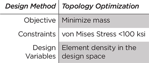
Constraints, or boundaries to the available design space, typically are established by part requirements and set the criterion for a feasible solution. Many constraints can be applied, but typical structural constraints are used to limit peak stress, deflection or mass.
Objective function is the goal of the analysis to be minimized (or maximized). Commonly, the objective of the optimization is to minimize mass or maximize stiffness, leading to lighter, more efficient structures.
At a basic level, the optimization process begins with an iterative search of the set of variables for feasible solutions within the defined constraints, to best satisfy the objective function. The objective function is evaluated using a numerical method such as finite-element analysis. Those regions of the part that are not allowed to change are designed into the ‘non-design’ space. These elements/ regions (typically interface surfaces/ mandatory component features) may not change shape nor topology with the analysis iterations.
Designers use two classes of structural-optimization methods—those for conceptual design and those for fine-tuning. When used in conjunction, these processes provide the best results. The goal of the conceptual analyses: determine the optimal material distribution for several sets of load cases and constraints. The results of this exercise then are used as a starting point for the design, as it defines the general regions where mass must be included to meet the defined constraints. The shapes and topologies that result from conceptual-design analyses allow designers to consider unintuitive, complex regions of the design space. These optimum material distributions are not biased by traditional ‘design for manufacturability’ rules.
Three Conceptual-Design Methods
 |
| Fig. 2 |
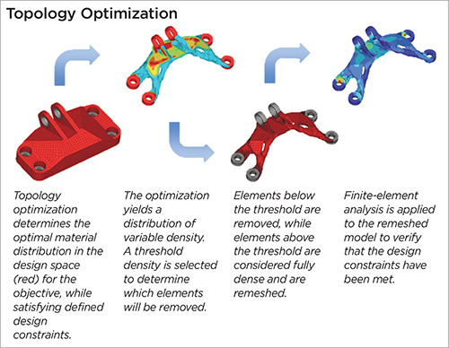
Topology Optimization—This optimization method allows for individual elements to be removed from the set of design elements. In doing so, part shape and topology are allowed to change. This method proves useful in determining the optimal material distribution for structural problems where a large design space is available. The most efficient material layout is determined based on user-defined design space, design targets and constraints of the component.
 |
| Fig. 3 |
Topography Optimization—This method finds use when determining the reinforcement beads or swages of thin-walled structures. Removal of elements is not optional with this method; rather, the thickness of the elements is varied to generate integrated reinforcements to achieve the objective of the analysis.
Free-Size Optimization—Designers use this method for generating optimal thickness distribution that meets design requirements.
After determining the optimal material distribution, the designer further refines the design by making limited changes to dimensions or model parameters. These methods may be applied to more accurately determine the localized features of the component.
Two Fine-Tuning Methods
Shape Optimization—Here we optimize the shape variables based on design requirements, to reduce stress concentrations.
Size Optimization—This process refines the model parameters, such as cross-section dimensions and thicknesses, to further optimize localized regions.
 |
| Fig. 4 |
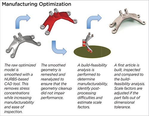
With the detailed design complete, the engineer turns to manufacturing optimization, evaluating the part within the context of additive-manufacturability rules and post-processing requirements, and for ease of inspection. By determining the constraints and limitations of the specific additive machine and process, we can apply those rules to the fine-tuned optimized design. Here we may alter orientation, change surface angles to minimize the support structure, make topology changes for post-processing accessibility, and add material for either datum points or for tooling to be used during post-processing.
Optimization Case Study
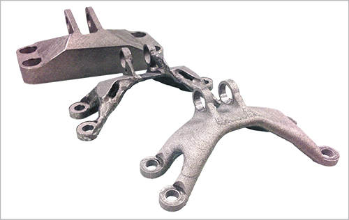
 The example provided here illustrates our approach to design and structural optimization for additive manufacturing. The original part design was heavily influenced by traditional manufacturability constraints. Since additive methods have more relaxed constraints, the part was redesigned using topology optimization.
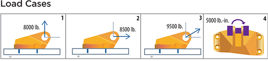
Note the load cases detailed in Fig. 1.
Fig. 2 describes the topology-optimization process, to determine optimal material distribution and threshold density, and finite-element analysis is used to verify that the model meets design constraints.
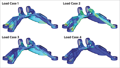
With the topology optimized, the designer then applies the load cases (Fig. 1) to determine corresponding stress results (Fig. 3). He then performs the manufacturing-optimization exercise (Fig. 4), giving consideration to manufacturability and inseparability, arriving finally at the optimum part design (Fig. 5).
 |
| Fig. 5 |
Tying it All Together
Whether the AM machine is printing simple blocks or fully functional and topology-optimized components, the designer has a lot to consider when developing a design-and-build layout. The creativity and opportunities that exist with the technology can be overwhelming, so it’s important to create guidelines and to follow best practices.
In addition, building demonstration or sample parts can go a long way when growing the internal design-team knowledge base. With the basic guidelines and limitations well understood, designers can step into a whole new world of opportunities when they consider pairing AM with design-optimization methods. It is there where designs can exploit the true benefits of AM, and create components that are efficient in terms of cost, quality and function. 3DMP
See also: LAI International Inc
Technologies: