Slug and Scrap Detection
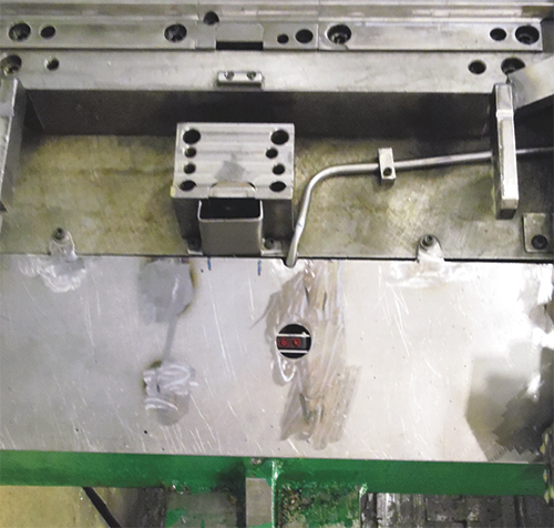 |
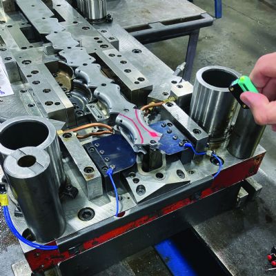
| Fig. 3—Hydraulic tubing protects the wiring of a part-out sensor embedded within the guiding exit plate. |
Tilley also has mastered the detection of slugs and scrap, by placing inductive proximity sensors—one per corner of the stripper—within blocks of steel, with their wiring carefully protected within channels (Fig. 2). When the stripper bottoms out, the four sensors need to be activated. If one or more of the sensors are not, then the die stops at the full open position and the location of the scrap or slug is announced by the die-protection control to the operator for its removal. Likewise, if one or more corners of the stripper arrive sooner than the rest, the sensors then can help to detect spring or nitrogen-cylinder failures behind the stripper. A double whammy of sensing.
Part ejection can be extremely tricky, as the parts can fly out of the die at high speeds and, most challenging of all, rotate and spin. This dynamic and fast-moving target can be quite difficult to detect and requires significant test-bench development to ensure there are no blind conditions where the optical sensor fails to detect the part. Likewise, the sensor applications specialist must ensure that the part can be detected regardless of which edge or surface is presented to the sensor.
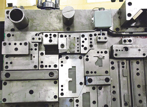 |
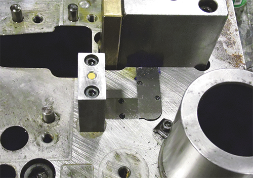
| Fig. 4—Where possible, Tilley routes sensor wiring through channels in the die. A protective screw-on cap shields the connector’s pins from accidental damage while the die moves in and out of the press and while in storage. |
As seen in Fig. 3, Tilley employs a reflective photoelectric sensor to perform part-out detection; note its respective cables protected within hydraulic tubing. Where practical, Tilley has carved channels into MIG’s dies to accommodate the sensor wiring. In many cases, however, this is not economically feasible, so he uses hydraulic tubing to protect the wires.
To merge the sensor wires into a single connector, Tilley meticulously routes the sensor cables within hydraulic tubing to a junction box where a military-style multiple pin connector is mounted (Fig. 4). The connector requires no soldering, so that the toolmaker responsible for the die can install the wires within their respective pins on the connector with a special crimping tool and service the connector—should it encounter damage —as needed. Note the use of the protective screw-on cap to shield the connector’s pins from accidental damage while the die moves in and out of the press and while in storage. MFView Glossary of Metalforming Terms
See also: Tecknow Education Services, Inc.
Technologies: Sensing/Electronics/IOT, Tooling
Comments
Must be logged in to post a comment. Sign in or Create an Account
There are no comments posted.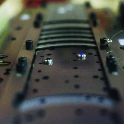 Sensing/Electronics/IOT
Press Controls and Sensors Series Part 4: Die-Protection Tro...
Jim Finnerty February 9, 2025
Eliminating Pressroom Waste—One Walk at a Time
Manuel Resendes June 10, 2025