Using Sensors Incompatible with the Control
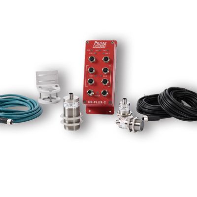
Electronic sensors offer many output options, but not all outputs are compatible with all controls. If in doubt, contact your control provider for assistance.
In-die sensors can perform a variety of functions, such as detecting cams returning to home position. Just be sure to avoid common mistakes that can derail a sensor program and waste time and money.
Not Planning for Sensor Wiring Prior to Install
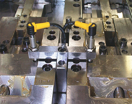
Cable damage accounts for more sensor replacements more than any other cause. Avoid damage by using die-mounted junction boxes and carefully planning the sensor-wire routes to protect the cables. Often, the most difficult part of installing a sensor is figuring out how to route the wire from the sensor to the junction box. Waiting until the die is assembled and the sensor installed is probably too late. All new die designs should have the sensor wires included on the CAD drawing.
Installing Normally Open Static Sensors in the Upper Die
A normally open static sensor only actuates when a problem exists. When such a sensor is installed in the upper die, the wire to the sensor eventually will break due to repeated flexing. To a die-protection control, a normally open static sensor with a broken wire looks exactly like the same sensor not detecting a problem.
A normally open sensor often can be converted to a normally closed sensor—always actuated and turns off when there’s a problem − by selecting the normally closed instead of the normally open output. The die-protection control will immediately detect a broken wire on a normally closed sensor, and stop the press.
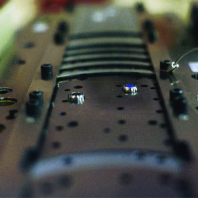
Here’s an example of a well-thought-out wire route. Cable damage accounts for more sensor replacements more than any other cause. Avoid damage by using die-mounted junction boxes and carefully planning the sensor-wire routes to protect the cables. All new die designs should have the sensor wires included on the CAD drawing.
Excessive Nuisance Stops
A machine stoppage initiated by the die-protection system when no real problem exists is known as a nuisance stop.
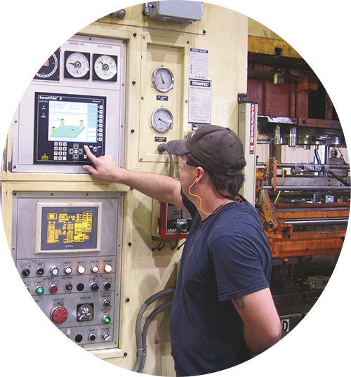
Upon the first nuisance stop, a conscientious machine operator carefully scrutinizes the error message from the controller, thoroughly inspects the press and die to locate the fault, and, only upon finding nothing wrong resets the error and restarts the machine. The next time a stop occurs, the operator might not read the message as carefully or inspect the machine as thoroughly. After that, you’re lucky if the operator gives a casual glance at the controller and die before pressing the reset button. Should the nuisance stops continue, it is only a matter of time before the sensor is disconnected and the system disabled.
What common practices may lead to excessive nuisance stops?
Using setup personnel to adjust the sensors. Adjustable sensors seem like a good idea—install them in a rough location and have the setup person fine-tune the sensor with each die run. But besides being labor-intensive, this practice can lead to nuisance stops. Setup personnel may lack the training or expertise to properly adjust all sensors for all conditions. The goal of any installation should be to select a sensor that never needs adjustment, and a location where the sensor will stop the machine only when a real problem is present. ‘Plug it in’ should be the only task for the setup person. A properly bench-tested sensor should be installed so that it will never have to be moved or adjusted. While an adjustment might come in handy initially, adjustability becomes a liability once the sensor runs correctly.
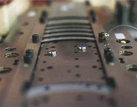
Place proximity sensors, so that the possibility of sensor damage is minimized should material or a tool locate out of position.
Moving sensors from die to die. New sensor users may try to save money by purchasing a part-ejection sensor with the intention of moving it to various dies as needed. In the end, this practice does not save money, and often leads to nuisance stops and damaged tooling. Select specific sensors for specific dies and leave them in place. You’ll avoid the expense of additional sensor-related setup time and the pitfalls of adjustability. Also, sensors moved from die to die tend to be compromise choices that can be shoehorned into many applications, rather than providing an ideal solution tailored to meet the exact needs of each application. And, suppose that the sensor you need is already in use on another die. Do you run without protection?
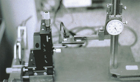
Requiring too much precision. Though desirable, a high level of precision is not always needed when installing sensors in the die. For example, with a bit of bench testing one could easily install a proximity sensor in the die to detect a strip misfeed of as little as 0.0005 in. But this almost guarantees ongoing nuisance stops because such a level of precision is unobtainable in most production environments. If you determine that the pilots can align the strip when it is misfed by ±0.010 in., then install sensors so that they won’t signal a stop unless the strip misfeeds by more than 0.010 in. This provides the setup person and equipment enough wiggle room to keep the process running while still protecting the die from misfeed damage. MF
View Glossary of Metalforming Terms
See also: Wintriss Controls Group LLC
Technologies: Pressroom Automation, Sensing/Electronics/IOT
Comments
Must be logged in to post a comment. Sign in or Create an Account
There are no comments posted. Sensing/Electronics/IOT
Eliminating Pressroom Waste—One Walk at a Time
Manuel Resendes June 10, 2025
Industry 4.0 Applications in the Sheet Metal Forming Industr...
Eren Billur March 27, 2025