


 This situation presents an opportunity to improve usability for the operators, ease press maintenance, address setup-reduction goals and reduce manufacturing costs. The press is a durable asset, and a control configured wisely to meet a stamper’s needs can make a significant positive impact for decades.
 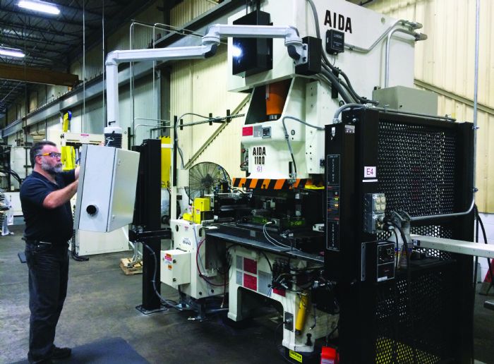 In this context, a press control includes the functions specific to running the press itself.
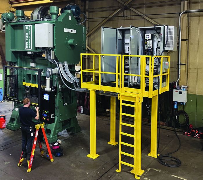 Inputs from sensors that monitor safety-critical press elements such as air-pressure sensors that keep tabs on the air pressure to the clutch/brake and counterbalance systems fall under this category. Additional inputs under the umbrella of safety include those that measure brake performance; die blocks; presence-sensing devices (such as light curtains); and safety interlocks. Safety outputs include control of the clutch/brake on a mechanical press—done via a safety-rated, dual-air valve.
Servo presses are equipped with equivalent control logic to start and stop motion with the drives, which may also include dual-safety valves for the safety brake.
- Subsystem controls are critical to running the press, but not specifically safety-related—for example, press lubrication. Small presses may have only a grease system. Large machines may apply grease plus run a fully recirculating oil system with pressure and plugged-filter sensors; flow sensors at key points on the machine; and even temperature gauging. The slide-adjustment-mechanism control, counterbalance control and cushion control fall into this area.
- Modes of operation are another consideration. For most models, the standard off/inch/single-stroke/continuous modes suffice. Due to the increasing use of press automation, specialized operating modes such as “auto single stroke” and “continuous on demand” are becoming more common.
Servo presses come equipped with additional modes as well, such as “step feed” and “return to origin” to take greater advantage of the technology.
- Diagnostic capability emerges as another important aspect of the press control. Often, today’s controls, equipped with substantial onboard diagnostics, including fault-log history, make solving problems quicker, shortening unplanned downtime events in the future.
Process Control
 Press control beyond the standard functions focuses on connecting the press to all of the auxiliary equipment and the tooling used in the stamping operation. These process controls allow metal formers to tailor the operation to the unique process elements and timing required for each tool running in the press. Process control expands beyond the press to the equipment around it and the stamping operation. Setup technicians and programmers interact with these elements the most.
Programable limit switches (PLSs) are output relays that the operator programs at the press. PLS channels direct the action. These switches connect into equipment around the press, such as the servo feeds, die-lubrication systems, air solenoids and robots. They provide commands for these devices to turn on and off, and at which specific points of the press cycle to control the timing of events relative to the closing and opening of the tool.
PLSs also provide simple position information to external devices. For example, they can define when the press’s slide resides at or near bottom dead center. Hydraulic and magnetic clamping systems rely on this function to ensure that someone doesn’t decouple a tool unless it is closed at the bottom of the stroke.
The simplest aspects of assessing which controller’s best for an application are the number of PLS channels, and whether that number can be expanded later.
In addition, metal formers should look at the logic capabilities. Simple PLS channels are programmed just to turn on and off, based on the press ram position. Some turn on at a specific position but also can be programmed to turn off after a designated period.
Other PLSs are equipped with more powerful options, such as turning off and on after a specified number of strokes; toggling between on and off; or even changing based on input transitions instead of press ram positions for instance, turning the PLS into a simple controller. These capabilities can vary depending on the control model and manufacturer.
Die Protection
Die protection monitors sensors in the tooling verify whether critical events have occurred. Failing that, the die-protection logic issues a stop command to halt press-ram travel, preventing tooling from crashing. For instance, it’s commonly used to check if the strip has advanced the proper distance in a progressive die plus or minus an allowable range. This mistake-proofing prevents costly repairs.
Another common sensor application verifies that the part has ejected safely out of the tool. Other uses include stripper-level sensors, cam-return sensors, broken-punch detection and critical in-die quality checks. Some of these sensors have evolved beyond preventing crashes to monitoring part quality in the tool.
Over time, these inputs have been used increasingly to monitor events outside the tooling, too. If, for example, the PLS turns the scrap system on and off with press motion, a sensor from the die-protection system can verify that it is operating. Low-level sensors in the die-lubrication system can be tied into die-protection logic so that an unattended press will stop if it runs out of lubrication. Another use case is a sensor at the coil line monitoring whether the coil strip runs out.
Die-protection capabilities vary wildly. Die-protection options start with the number available and capacity to add more if required. Two additional significant capabilities: whether it accepts PNP or NPN sensors, and the number of sensor-logic types. Some are quite simple, designed for the most routine uses with no diagnostic feedback. Others with more sophisticated capabilities are transitioning to provide assistance to the programmer to set up programs accurately and quickly.
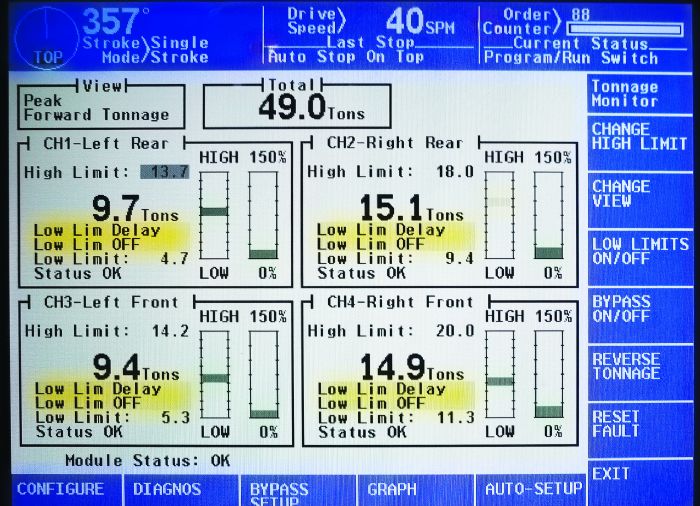
Tonnage monitoring is another important aspect of process control, typically employing strain-gauge sensors mounted to the press frame or connection points to measure the force exerted on the tooling by the press. The operator sets control limits for high and low force for normal operation, as well as for maximum reverse tonnage. That allowance is needed because the force required to produce a good part varies widely from tool to tool—even changing as a tool wears gradually. In addition, variability is inherent in the incoming coil or metal blanks because they vary in thickness and mechanical properties.
Tonnage monitors come in two types: simple peak tonnage and signature analysis. Peak-tonnage monitors track the peak force point in the stroke for each strain gauge, then allow operators to set high and low limits at that stroke position. Signature-analysis units provide greater capability by graphing the tonnage compared to the press position for each strain gauge. This allows stampers to capture more refined data of the tooling features—their wear and even their presence. Both types are designed to monitor for changes in force and stop the process if it varies out of control limits. The signature-analysis units can catch more issues.
Shut-Height and Counterbalance Control
Shut-height control, for adjusting the shut height or die height, is part of the press control; however, it also is a variable setting dictated by the needs of the tooling. This makes shut-height control part of process control as well. Each tool will require variation in height and adjustments to its nominal setting to achieve a good part. This is a critically important part of the run setup. Increasingly, this function is automated by process controls and stored in a recipe to ensure fast, repeatable setups.
Counterbalance and cushion air control are part of the press, but settings tie directly to the unique needs of the tooling being run. The settings must be changed as part of the die-installation and setup process. Also, like the shut-height control, these functions and their settings commonly are automated.
Communications with external devices are required when presses integrate with external equipment, such as coil lines and transfer systems. In addition, multiaxis robots find increasingly common use to feed and transfer parts into or through the tool stations and out of the press. That equipment’s unique settings required to run each tool and reduce setup times are stored in that equipment, separate from the press control. Modern controls can send recipe commands to the external equipment, ensuring all the equipment required is configured for the job running.
In addition to auxiliary equipment, manufacturers often use plant-wide production-monitoring software. Those systems seek information such as the current recipe number in production, running status, production speed and production counter-values. The controls with built-in communication protocols will support this sort of interface to the network.
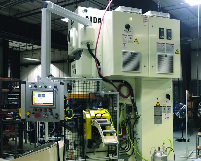
The physical layout matters too. Positioning a large console on the floor may be easier for the builder to install but will be in the metal former’s way. An optimal layout comprises locating large panels up and out of the way on mezzanines, and consolidating operator controls into one smaller and movable master operator station.
Last but not least, stampers should examine the long-term cost of ownership. Repairs and components’ obsolescence factor into future replacements and costs.
Bringing the various stakeholders who use the controls together—operators, setup technicians, toolmakers, manufacturing engineers, maintenance staff and IT—brings optimal results. Never underestimate how helpful the team approach can be, or the impact that it can make. MF
View Glossary of Metalforming Terms
See also: TCR-Integrated Stamping Systems
Technologies: Pressroom Automation
Comments
Must be logged in to post a comment. Sign in or Create an Account
There are no comments posted. Sensing/Electronics/IOT
Press Controls and Sensors Series Part 4: Die-Protection Tro...
Jim Finnerty February 9, 2025
Press-Line Controls Under One Umbrella-An Ideal Solution
Lou Kren September 27, 2024
 Sensing/Electronics/IOT
Press Controls and Sensors Series Part 3: Best Practices for...
Jim Finnerty August 31, 2024
 Pressroom Automation
Next-Generation Motion-Control System for Basic Automation A...
Friday, June 27, 2025