Managing Horizontal Forces in Stamping Dies—Part 2
June 1, 2020Comments
Last month’s column addressed the management of horizontal forces in the dieset. This month: The prevention of die-component shifting due to horizontal die forces.
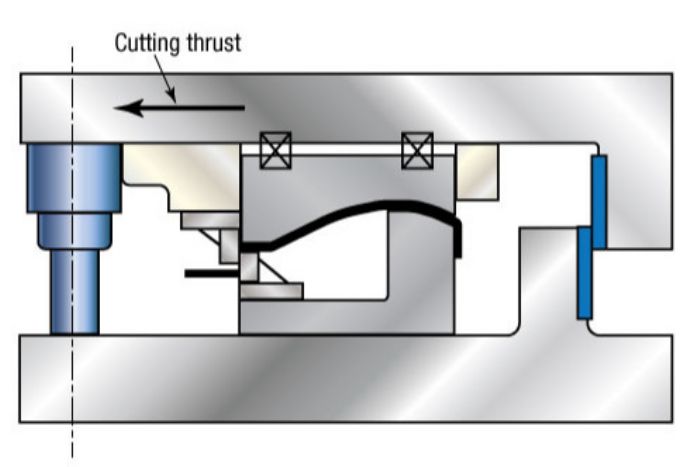 Dies experiencing significant side loads often have multiple causes, including: poor alignment of die components during construction; misalignment resulting from a bad hit or die crash; shifting of components due to angular contact between angular form steels; nonsymmetrical forms or draws where the punch and die are loaded off-center at initial contact; and cutoff, trim, bending and flanging operations where forces act on only one side of the die steel.
Shifting of Die Components
Maintaining alignment and designed clearances between die components is paramount for long die life and consistent part quality. When a die component shifts, alignment and clearances can alter significantly enough to cause galling or shearing damage to the tooling.
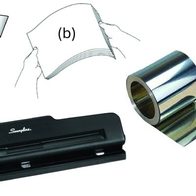
Shifting of die steels is prevented through a combination of forces applied normal (perpendicular) to the mounting surface and the friction generated between the two surfaces. Friction occurs because the surfaces in contact are not smooth. Small ridges on the mating surfaces lock together, restricting movement. For movement to occur, these ridges must be broken off (sheared) by a horizontal force of sufficient magnitude. The force required to move two sliding surfaces over each other, divided by the force holding them together, is known as the friction coefficient (µ).
Intuitively, we know that higher frictional forces better prevent the shifting of die components. Now let’s covert this intuitive understanding into something more useful and easy to remember:
Friction is fun, or F = µ N
Where F is the static frictional force, µ the friction coefficient and N the normal force.
The friction coefficient for two pieces of steel in contact, clean and dry, is approximately 0.75. With each surface lightly oiled, the friction coefficient could approximate 0.15.
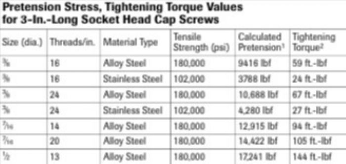 The accompanying table depicts the calculated pretension stress and the tightening torque values for several 3-in.-long socket head cap screws. Several viable options exist to meet the 50,000 lbf requirement: Five 3⁄8-24 alloy-steel cap screws, torqued to 67 ft.-lbf; four 7⁄16-14 alloy-steel cap screws, torqued to 94 ft.-lbf; or three 1⁄2-13 alloy-steel cap screws torqued to 144 ft.-lbf.