How Valuable Is One Data Point?

March 1, 2008
0
Comments


One data point can be priceless—especially if it provides the last piece of information needed to solve a critical problem or win a million dollars. In the physical world, however, one data point actually defines very little. Through one data point an infinite number of lines—both straight and curved—from any direction are possible. Two data points define a straight line. However, through this line an infinite number of planes are possible. One needs three data points to define a single plane.  

Four data points all on the same plane provide a measure of redundancy or validation. Each point is an accuracy check of the other three. However, sometimes too many data points can create a problem. If the fourth data point is out of the plane generated by the other three, a three-dimensional surface exists. Common knowledge tells us that a three-legged table, stool, tripod, etc. is stable. Most everyone knows what happens when a fourth leg of a table or chair differs dimensionally from the other three.

How does this discussion relate to metalforming? Unfortunately, only one data point is the basis for too many critical press-shop decisions. The highest value of strain (amount of deformation) in a stamping triggers a massive effort to reduce the strain at that data point. Unfortunately, a single data point does not provide clues to the cause of the high strain.

Fig. 1 two identical peak strains (x) have different causes.
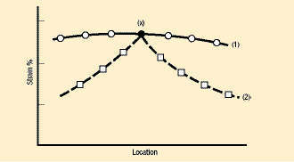
Fig. 1—Two identical peak strains (x) have different causes. Case 1 has an excellent flat distribution of strain but a very high restraint to material flow into the zone. Case 2 suggests some tool feature at the peak strain is the probable cause. A single data point would not reveal this difference.

Fig. 1 shows two possible series of additional data points around the measured data point (x). Case 1 shows six data points with the same level of strain as (x). Reducing the strain only at point (x) is not very effective because the high strain on either side of (x) would remain. This distribution of strain indicates a highly desired uniform level of strain over a large area of the stamping. However, lack of material flow from the surrounding area or excessively high tensile stresses at the ends of the uniform strain zone are causing the high strains.

In contrast, Case 2 shows a highly localized gradient of strain at data point (x). A common cause is an underlying feature in the tooling. Inspection of the tooling beneath any sharp gradient should be the first step in troubleshooting. The tooling feature may be a requirement of the part, such as a sharp character line, a tight bend radius, a small embossment or any other feature requiring sharp lines. Other times the problem feature in the tooling may be independent of the part. Examples include a radius and straight section not meeting tangentially, a joint between two tooling segments creating a sharp line of radius change, or a concentrated change in section lengths. A sharp gradient of thickness reduction usually accompanies these highly localized areas of strain.

Another common problem in metalforming is the lack of information about the forming severity of the stamping. Imagine you are walking in the woods where a big camouflaged pit is located to trap wild animals. Knowing your exact location is great but not much help if you want to avoid falling into the pit. Only after you fall into the pit do you have the second necessary data point. Knowing the strain at some location in the stamping is a basic requirement. If the stamping breaks, one now knows the second data point. Knowing in advance the strain when failure will occur allows one to determine a proximity to the failure strain in a stamping that has not yet failed. If the safety margin (distance between the two points) is insufficient, the two data points provide tracking information during changes to the forming process.

Fig.2 Peak strain measurements and maximum allowable stretch
Fig. 2—Peak strain measurements and maximum allowable stretch (from a forming limit diagram) are plotted to show the rapid decrease in safety margin as the yield strength increases. All steels were formed without process or tooling changes.

A larger group of data points allows for comparing the strain at some point in a stamping to the failure strain for different process conditions. Fig. 2 provides an example of applying higher strength steels to a specific stamping. As yield strength increases, the strain level usually increases as the work hardening exponent (n-value) decreases. To make the problem more critical, the allowable strain defined by the onset of failure decreases with increasing yield strength and a decreasing work hardening exponent. The graph indicates failure yield strength and the yield strength for different safety margins. Fig. 2 data are invaluable to product designers.

Fig. 3 Two different locations in a stamping had the same strain value
Fig. 3—Two different locations in a stamping had the same strain value when the stamping was at home depth. However, the strain histories were very different.

Sometimes a single-strain data point taken from the stamping at home depth does not provide sufficient information to solve a particular stamping problem. Often a series of incremental or breakdown stampings are made to study how the material deforms as punch depth increases. Sometimes only a visual examination is made of the stampings and strain data points are not obtained. Other times troubleshooters obtain strain data points but do not plot them, thereby losing trend information. Fig. 3 shows two locations on the same stamping having the same final strain level. However, the histories of these two identical final strain points reveal major differences in strain paths—key information for troubleshooting. 

Unfortunately, too many part designers, tool designers and press shops do not have any data points. At the other extreme, other designers and press shops have as many data points as they need because they form their parts in the virtual world while the part design is still flexible. MF

Industry-Related Terms: Bend Radius, Case, Form, Forming, Lines, Point, Surface, Thickness, Work Hardening
View Glossary of Metalforming Terms

Technologies: Materials

Comments

Must be logged in to post a comment.
There are no comments posted.

Subscribe to the Newsletter

Start receiving newsletters.