Don't Assume Yesterday's Corrective Actions Will Work Today
April 1, 2017Comments
Metalformers occasionally try to apply press-shop practices that have worked in the past when attempting to solve current metalforming challenges.
Does this sound familiar?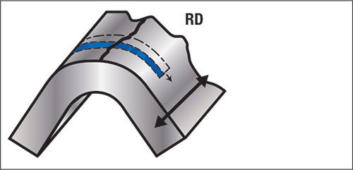
Fig. 1—Bend axis parallel to rolling direction increases cracking potential because tensile stress is across the long inclusion.
“I experienced this same problem 22 years ago with a part almost identical to this one. I simply made an adjustment to the tool; I can make the same change to this tool.”
Such thinking creates some major issues:
1) Were the 60 or more system inputs measured and recorded from the old part?
2) Do these inputs exactly match the same inputs of the current part?
3) If not, why would making the same adjustment 22 years later correct the current problem?
Consider these enhancements to steel properties that require a new approach to press-shop problem-solving.
Bending
Early steel had sulfur-based inclusions (primarily manganese-sulfur) that ran parallel to the coil-rolling direction (Fig. 1). If a blank was formed by bending parallel to the inclusion, a crack or even a through-thickness split would occur at the inclusion. To avoid these cracks, blanks were formed by turning them 90 deg. Today, the amount of sulfur has been greatly reduced in most steels and the inclusions have disappeared. This allows multidirectional steel alignment and bending.
Stretching
At the start of deformation, some parts form a narrow zone of stretch that can range from a tube to an edge contraction. This happens mostly for lower values of n-value found in some high-strength low-alloy steels. The higher the strength, the lower the n-value. Newer dual-phase steels from the advanced-high-strength-steel (AHSS) group have especially high n-values in the strain range of 2 to 5 percent that help to reduce peak strains. 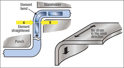
Fig. 2—Which tears first: A or B?
Pulling Over a Radius
Take a strip or small width of steel sheet and pull it from the upper flat surface around a 90-deg. radius and you end up using tension to straighten the sheet as it leaves the radius (Fig. 2). To test your knowledge, will the strip break on the outside surface (A) or on the inside surface (B)? Most will answer the outside surface, but the correct answer is the inside surface (B).
Here’s why. The sheetmetal from the blankholder moves over the 90-deg. radius. The outer surface is in tension and elongates to cover the increased surface of the curvature. As the sheet leaves the curvature it straightens and enters compression. Therefore, no failure occurs. However, the inner surface is on the opposite side of the centerline of the sheet—it goes into compression and resists material flow. Soon the flow stops and the sheet tears. 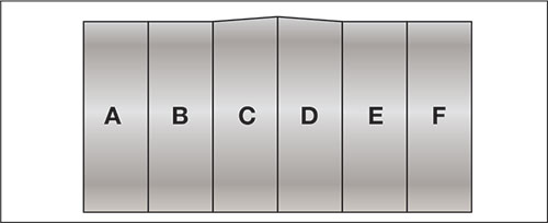
Fig. 3—Master coil cut into narrow coils.
Right- and Left-Hand Steel
This is a common cause of production problems. Mills run steel coils through many sets of rolls. Each roll has a job—reducing the sheet thickness, creating a surface pattern, etc. Coil-feed speed starts slow and quickens during processing. To control coil alignment moving through the rolls, the centers of the coils are made thicker than the rest of the coil. Grooves in the rolling mills guide these thicker zones.
Some companies use this center line to cut the coil into two halves. They then create one coil from each half—right- and left-hand steel. Stamping dies then are engineered to accommodate the thicker edge—left-hand coils are stamped in left-hand dies and right-hand coils are stamped in right-hand dies. Problems arise when the press shop runs short of right-hand coils and attempts to make parts out of left-hand coils, and vice-versa; it doesn’t work.
Another thing steel mills do: take full-width coils and cut them into narrow subcoils (Fig. 3), for use on smaller jobs. Stampers can obtain from the mill all of the relevant steel and die information if the mill properly labels the coils as they are cut. So, if for example coils C or D are having problems, the stamper should first evaluate the tracking peak (center). If coil F is having problems, substitute coil A for coil F. If the problem disappears, the problem could be due to the edge quality of the master coil. MF
View Glossary of Metalforming Terms
Technologies: Materials