Metal Properties: Elastic Modulus
July 26, 2022Comments
Interatomic bonds hold atoms together, and metal flow requires breaking these atomic bonds. During the metal stamping process, when a punch first contacts a sheet metal blank and prior to these bonds breaking, the forces produced move the metal atoms away from their neutral state and the blank begins to deform. At the atomic level, the applied force leads to elastic stresses that result in deformation known as elastic strain. Forces within the atomic cell are extremely strong; high values of elastic stress result in only a small amount of elastic strain. Removing the force while causing only elastic strain allows atoms to return to their original lattice positions, with no permanent or plastic deformation. The stresses and strains return to zero.
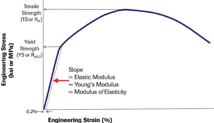
Hooke’s Law characterizes the linear relationship between stress and strain at these low strain values where atoms experience only a small deviation from their neutral positions. The initial linear section of a stress-strain curve highlights this proportional relationship. The slope in this area is called the elastic modulus, Young’s modulus or the modulus of elasticity (typically abbreviated as E). Beyond this linear region, strain becomes nonproportional with the onset of plastic or permanent deformation (Fig. 1).
 The atomic structure of the metal influences the slope of the modulus line. Most steels have a body-centered cubic structure—an atomic unit cell with one atom located at each corner of a cube and one atom in the center of the cube. The elastic modulus for steel typically is 210 GPa (30 million psi). In contrast, aluminum and many other nonferrous metals have one atom at each corner of the cube and one on each face of the cube, creating what is known as a Face Centered Cubic (FCC) atomic structure. Many aluminum alloys have an elastic modulus of approximately 70 GPa (10 million psi).
Springback
The deformed panel shape under full press load at bottom dead center combines elastic and plastic stresses and strains. The formed part out of the press incorporates the permanent deformation of the blank, with the release of the elastic stress and strain being the root cause of springback. The difference in atomic structure of steel and aluminum alloys, and the associated difference in elastic modulus, form the basis for the different springback response between these sheet metals.


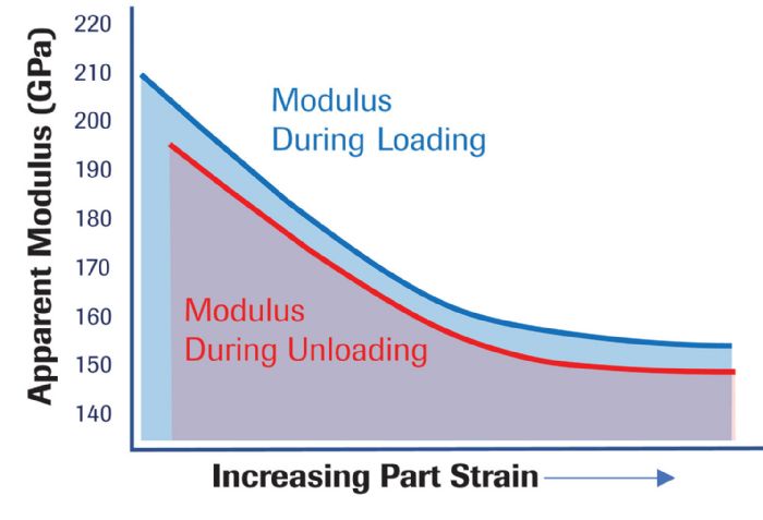
 Forming-simulation analysts incorrectly treat the elastic modulus as a constant. While the standard 210-GPa and 70-GPa values serve as reasonable approximations for generic steel and aluminum alloys, the modulus can vary by as much as 10 percent for some grades, depending on the orientation relative to rolling direction. Complicating matters: The magnitude of variation as a function of orientation relative to the rolling direction is not constant between all grades.
 Webinar
