Avoiding the 7 Deadly Sins of Stamping: Part 4
November 21, 2024Comments
To design, build and troubleshoot a deep-drawing process, tool- and diemakers must have a fundamental understanding of the principles of sheet metal flow. In this article, I will discuss the drawing of round parts (this issue) and square parts (next issue). Once you understand these principles, you can use the same basic principles for almost any given geometry.
Drawing vs. Stretching
 Many people often confuse stretching operations with drawing. These two metal forming operations are distinctly different, even though they share similarities.
Stretching can be defined as an increase in the blank’s or sheet metal’s surface area as a result of tension. During a stretching operation, the sheet metal thins. If it thins too much, it can rupture or split. The amount of stretching that can occur depends upon numerous factors, including part geometry, material type and thickness, forming speeds and frictional values. Shallow-formed parts such as automobile hoods and roofs often are made through stretching only. Stretching the sheet metal is necessary to meet the surface requirements and to change the material’s physical properties by work hardening it. This helps make it dent-resistant.
Drawing is the displacement of material into a cavity or over a punch as the sheet metal flows. Because the material always is in tension as it’s being pulled into the die, a certain amount of stretching always will occur. The basic idea of drawing is to create most of the part geometry not by stretching it, but by feeding material into the die. This helps reduce or prevent the amount of stretching that occurs.
Round cups are made primarily using the drawing process. Many deep-drawn parts require a delicate balance between the amount of sheet metal flow taking place and the amount of stretch occurring. Many automotive parts, such as inner doors, wheel housings and other deep-formed products, often rely on this delicate balance. If the part stretches too much, it might split; excessive overfeeding of material inward may cause wrinkles or other cosmetic defects.
Sheet Metal-Flow Basics
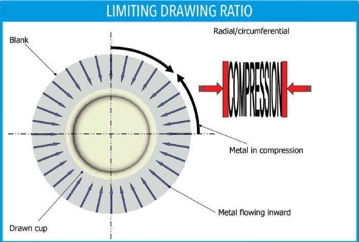
Beginning with the process necessary to draw a round cup, the basic idea is to pull the circular blank into the cup-shaped cavity using a punch that is the reverse of the inside shape of the desired cup. The blank must be larger in diameter than the cup’s finished diameter. For the blank’s diameter to be reduced, it must be pulled into the cavity simultaneously. Squeezing the sheet is called compression. If compression occurs all the way around an axial symmetrical part such as a cup, that is “circumferential compression.” Remember that when sheet metal is forced into compression, that creates a resistance to flow. It is the compression that’s creating the resistance (Fig. 1).


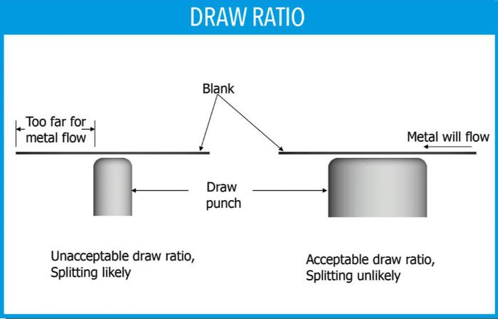
 If there is excess resistance, the metal ultimately will stretch and potentially could rupture. For this reason, carefully limit the amount of surface area in compression by maintaining a direct relationship between the diameter of the forming punch and the diameter of the blank. This critical relationship is referred to as the limiting drawing ratio (LDR). In other words, if the drawing punch is large enough or close enough to the blank edge, this will limit the amount of compression and the metal likely will flow inward. If the blank is too large in relationship with the drawing-punch diameter, the resulting excess compression will generate great resistance to flow and most likely result in excessive thinning, and potential splitting (Fig. 2).
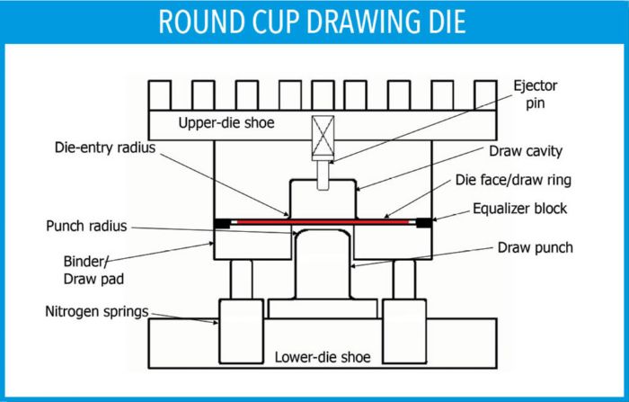
 It also is important to understand that compression not only creates a resistance to flow but it can result in wrinkles and even double-thickness problems. This is why a high-pressure drawing pad, often referred to as the binder or blankholder, is necessary. A drawing pad prevents the sheet metal from wrinkling by restricting the gap in the blank area that is in compression to only slightly thicker than the sheet thickness. In short, the spacing between the two surfaces won’t allow the material to wrinkle. That spacing is maintained by using a series of special blocks mounted outside of the blank, called equalizers or standoffs. If the compression is extreme, the sheet actually can get thicker than its original thickness (Fig. 3).
 Webinar
