Avoiding the 7 Deadly Sins of Stamping: Part 5 Metal-Flow Principles for Square Parts
February 11, 2025Comments
To design, build and troubleshoot a deep drawing operation, tool- and diemakers must have a fundamental understanding of sheet metal-flow principles. In the previous article, I discussed the drawing of round parts and defined the difference between drawing and stretching. Here I will discuss the process of drawing square and rectangular shapes.
Compression Vs. No Compression
Previously, we discussed radial compression. We highlighted that when sheet metal is forced to compress, it will resist flowing. The curved profile radius creates the compression. Conversely, sheet metal flowing into a die not under compression has very little resistance to flow. Why? Because the material bends and unbends as it travels into the die cavity. It is not forced to squeeze together; therefore, very little resistance to flow occurs.
Dissecting A Square Shape
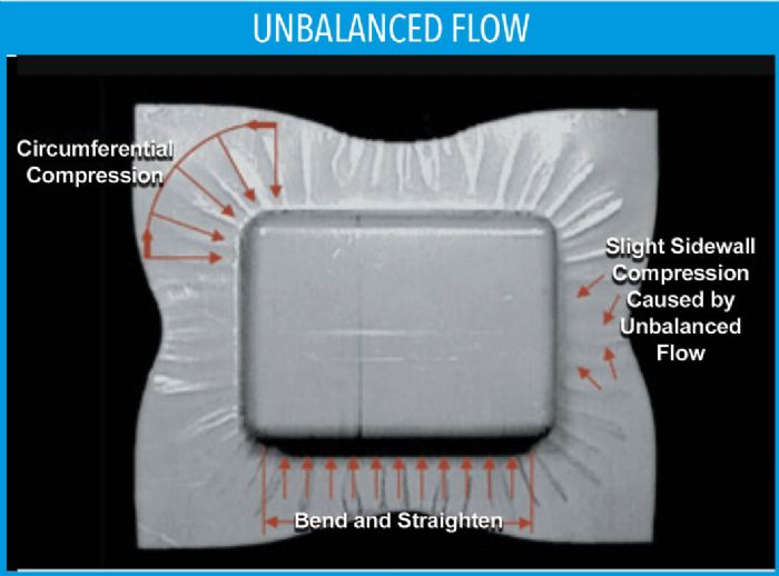 Rather than look at a drawn square or rectangular part as a whole, dissect it into straight lines and corners. Essentially, a square or rectangular drawn part with radial corners can be dissected into four quadrants of a round drawn part connected by four straight lines. Because the corners have a curved radial profile, the sheet metal is in radial compression. That explains why far less material flows in the corners than in the side walls. The side walls offer very little resistance to flow because very little or no compression takes place; the sheet metal flows in more on the sides than in the corners. (Fig. 1).
Balancing Metal Flow Values
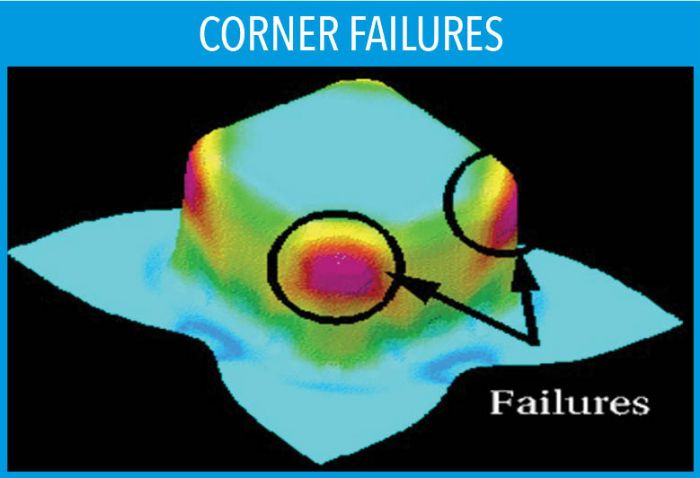 If an insufficient amount of sheet metal flows into the corners of the box, it may result in excessive thinning, necking or splitting. (Fig. 2). Too much material flowing into the side walls may result in loose sheet metal, curvature of the sidewalls or an effect referred to as “oil canning.”
To reduce the possibility of thinning, necking or splitting in the corners, one solution involves changing the limiting draw ratio. Because the punch geometry cannot be changed, the only alternative is to cut or miter the blank’s corners. This changes the punch-to-blank relationship—not by increasing the punch size but by decreasing the size of the blank’s corners. Mitering the corners is a common method to increase material-flow values in the corners (Fig. 3). In addition, increasing the die-entry radius size can help promote material flow in the corners.
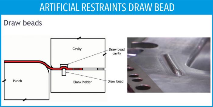 In the side wall with no flow resistance, it often is necessary to add what is called an artificial restraint, defined as anything added to the draw pad or outside of the part to help reduce or stop the amount of material flowing inward. A draw bead represents a very common type of artificial restraint. Natural restraints are a product of the part design. For example, a corner profile radius in a rectangular drawn part naturally causes some resistance to flow because of compression created by the feature. Draw beads create a restraining force by causing the material to bend and unbend prior to coming into the cavity or over the punch (Fig. 3).
 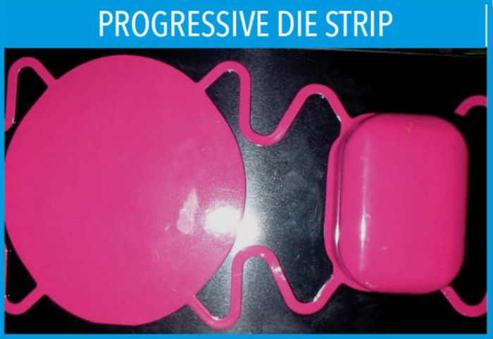 Keep in mind that as the corner profile radius of the rectangular shell increases, the depth of forming that can be achieved in a single operation also increases. As the profile radius increases, the amount of compression occurring in the corners reduces. Compression creates the resistance to flow; subsequently, reducing the compression increases the amount of flow. For instance, a rectangular box with a 1-in. corner profile radius can be drawn considerably deeper than the same box with a 0.25-in. profile radius.