


Dome Embossments Provide Forming Knowledge
August 1, 2012Comments
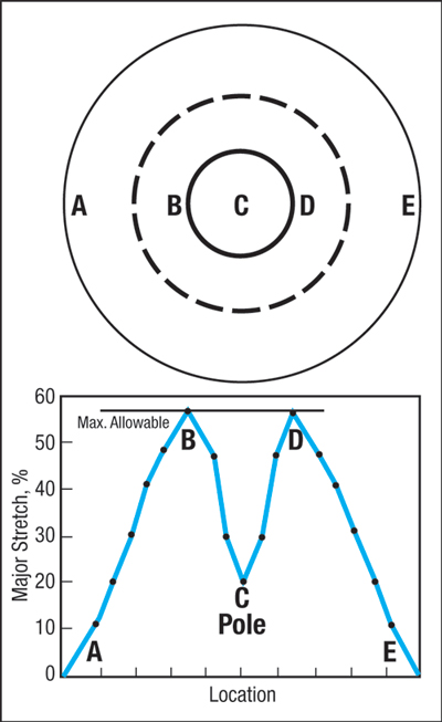 |
| Fig. 1—Punch friction reduces material stretch at the pole and generates a ring of thinning further down the dome wall. |
Hemispherical embossments are found in millions of sheetmetal stampings. Though simple in shape, their deformation process can be complex. Ask tool and die personnel where the dome may fail and they’ll note several possibilities–straight line across the pole, the pole blows open like a hole expansion, a circumferential ring near the pole, or a ring near the die radius. All are possible depending on punch design, lubrication and sheetmetal properties. Many laboratories have built special 4-in.-dia. hemispherical-dome testers to generate forming-limit diagrams (FLDs), biaxial stress and strain equations, friction evaluations and other formability information.
The typical dome test begins by clamping a blank between an upper and lower blankholder containing a lock-bead circle to prevent blank pull-in. The upper blankholder usually serves as the die ring. This allows the pull-over hemispherical punch to deform the dome upward through the die ring, in visual sight of the operator or of strain-recording cameras. Looking directly down on the formed dome (upper sketch in Fig. 1), failure usually occurs as a ring of thinned material between the dashed ring (poor lubricant) and the solid ring (excellent lubricant). Thinning in the neck continues until the material tears.
Why not a failure at the pole? Because deformation at the pole is very low compared to deformation in ring B-D (bottom graph in Fig. 1). Upon contact with the punch, friction restrains the ability of the pole material to stretch. Sheetmetal without punch contact stretches more easily, developing a stretch gradient. This gradient increases with punch travel until the stretch exceeds the forming-limit curve and fails. A lubricant with a higher coefficient of friction restrains the stretch even more for material contacting the punch. This forces the stretch gradients to move further a from the pole (dotted ring) where the forming-limit is lower.
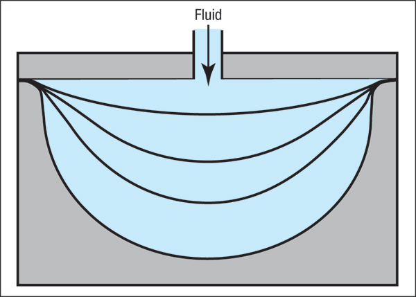 |
| Fig. 2—Replacing a rigid punch with a flexible fluid allows sheetmetal to stretch more uniformly as the blank transforms from flat to the final cavity shape. |
Is there a lubricant with a very low coefficient of friction as to allow the stretch to peak and fail at the pole? Some stamping plants use water to form domes and many other parts. Called hydroforming, the punch is replaced with zero-friction water. The pole begins to stretch immediately and continues to be the site of maximum stretch. Since failure requires a line of thinning, a small ring of thinning around the pole fails rather than a point eruption at the pole. One exception: a straight-line tear parallel to the rolling direction, occurring at or near the pole. These tears result from a long, hard inclusion within the material, or from a severe surface scratch that acts as failure notch.
One major problem with forming sheetmetal over solid punches and other tools is instantaneous localization of deformation. When a flat blank contacts a curved punch surface, the blank curvature instantaneously grows from Rc = 0 to Rc of the punch. This highly localized sharp bend creates tensile stress in the outer bend surface, adding extra stress and additional stretching at the bend. Once bent, the shape of the sheetmetal is locked and subjected to punch conformity and friction.
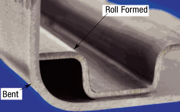 |
| Fig. 3—Minimum corner radius for 200,000 Psi yield strength martensitic steel created by bending and roll forming. WorldAutoSteel - AHSS Application Guidelines 4.1 |
Hydroforming can completely change the material’s deformation. At the start of forming (Fig. 2), the entire blank within the die opening begins to uniformly stretch without gradients. The blank continues to stretch until the die cavity is completely filled. If the cavity is too deep, the excess stretch exceeds the FLD and a thickness neck/failure occurs.
Hydroforming is not restricted to water. Laboratories have formed domes of numerous shapes with a lubricated rubber disk of the correct durometer and volume to fill the cavity. Placed on a flat-bottom punch, the rubber disk is compressed by the die to change shape like a fluid. Other deformation modes simulating hydroforming include explosive forming and electromagnetic pulse waves. Need to form one 20-ft.-dia. hemisphere? Try using explosive forming with a female die made from concrete.
The instantaneous bending of the sheetmetal upon punch contact described above also occurs in traditional bending operations. In contrast, the rollforming process allows the gradual shaping of the bend with unrestricted edge motion as the workpiece material moves through a series of roll stations. Fig. 3 shows the improvement in minimum corner radius for 200,000-PSI yield strength martensitic steel formed by rollforming, compared to traditional bending. Understanding the mechanics of forming often allows production of more difficult stampings with less forming severity. MF
On August 21-22, Stuart Keeler and Peter Ulintz will present a comprehensive High Strength Steel seminar at the Holiday Inn Detroit Metro Airport. Complete information can be found on www.pma.org.View Glossary of Metalforming Terms
Technologies: Lubrication, Materials, Other Processes


 Video
Video