Managing Horizontal Forces in Stamping Dies—Part 1
April 30, 2020Comments
A well-constructed, symmetrical blanking die, with no shear and a well-aligned press ram, will result in minimum horizontal loads during the cutting process. In many dies the horizontal thrusts due to punch-to-die clearances are the only side forces present. Dies that experience significant side loads often have multiple causes, including poor alignment of die components during die construction; misalignment resulting from a miss-hit or die crash; angular contact between surfaces, such as angular form steels; nonsymmetrical forms or draws where the punch and die are loaded off-center at initial contact; the use of shear or angular cutting faces to reduce cutting forces; and cutoff, trim, bending and flanging operations where forces act on only one side of the die steel.
Guide Pins
Guide pins and bushings guide the upper and lower die halves. For precision or master diesets, the pin-to-bushing clearance measures less than 0.0005 in. dia.; commercial-dieset clearances measure less than 0.001 in. dia. A guide pin primarily aids in die construction, maintenance and setup. Guide pins are not intended to absorb horizontal forces (side thrusts) or realign the ram in a poorly maintained press.
Since alignment is a matter of maintaining clearance, the running clearance of the guiding elements must be closer than the design clearance between components in the die. The following example, adapted from Techniques of Pressworking Sheet Metal (Prentice-Hall 1974 pp.424), illustrates this concept:
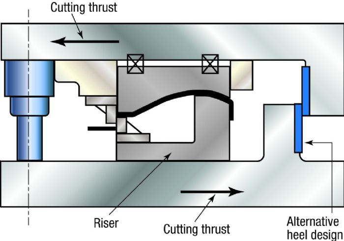
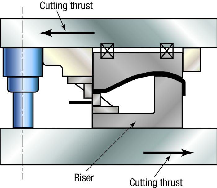 The cutting steels act along one edge of a formed stamping (Fig. 1). This type of die can produce an increase in cutting clearance due to side thrusts generated by the cutting action.
At least four components in the die assembly can cause an increase in cutting clearance: two guide pins, the punch steel and the die steel. For simplicity, assume that the riser remains rigid and does not bend under load.
Step 1—Determine the allowable clearance variation:
Sheet metal thickness, t = 0.035 in.
Cutting clearance = 10 percent of t = 0.0035 in.
 Step 3—Determine allowable guide-pin deflection: