Jim Ward Jim Ward
Manager of Manufacturing

The Basics of Coil Processing, Part 1: Unwinding the Coil

January 1, 2012
0
Comments


Modern coil-handling and feeding equipment has dramatically increased the efficiency and throughput of pressrooms around the world, as well as helped to eliminate the dangers and repetitiveness of hand feeding. Metalformers can select from among a variety of coil-feeding methods and types of equipment to accommodate their unique needs. When doing so, they must consider several parameters to ensure selecting a system that best meets the requirements of the application, including price, operating cost, coil weight, material type and thickness, feed length and speed requirements, material finish, floor-space availability and controls compatibility.

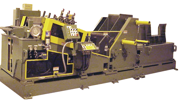
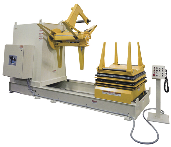
Fig. 1—A combination cradle/straightener unwinds the coil off of the top to a powered straightener and into a horizontal loop. Of the three coil-cradle configurations, this style requires the greatest amount of floor space due to the horizontal loop.
In this series of articles, we will discuss such basic operations as unwinding and straightening the coil, and feeding the press. Along the we will discuss the various types of equipment used for each process, helping to provide basic guidelines for investing in new coil-processing lines.

The focus of this article: The various approaches to coil unwinding— coil cradles (or coil boxes), centering reels and pallet decoilers. Look for part two later this year, where we will explore straightening options for coil lines.

Coil Cradles

Coil cradles hold a coil by the outside diameter, cradling it on powered rollers called nest rolls. This approach primarily finds use in medium- to heavy-gauge applications when material marking is not an issue. The cradle contains the coil within a box or framework that provides protection for the operator, by preventing the coil from telescoping. The outer wrap is contained between the weight of the coil and the nest roll as it unwinds, helping to prevent clockspring as well as controlling the coil for threading, particularly useful when feeding heavy-gauge or high-strength materials. However, this same feature also can cause problems with thin or cosmetically sensitive material, as it tends to mark or distort the sheetmetal.

A rule of thumb: Avoid use of coil cradles for processing material less than 0.06 in. thick.

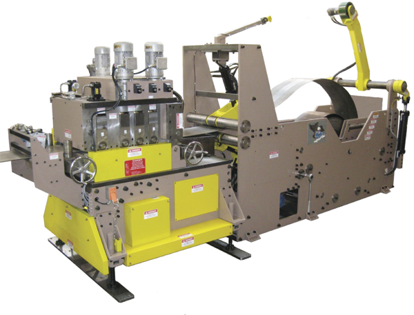
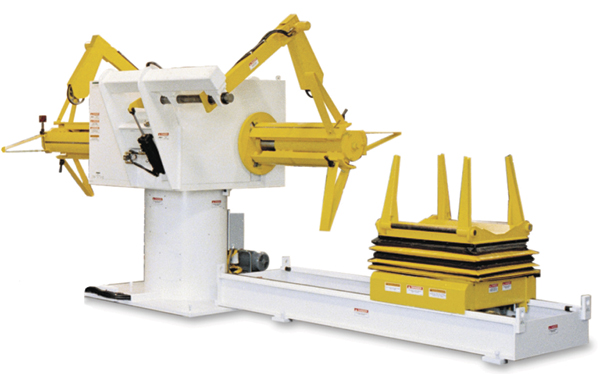
Fig. 2—The third type of cradle—a cradle-feeder straightener—unwinds, straightens and feeds directly into the press without the need for a slack loop, making it a very compact and self-contained coil-feeding system.
Another disadvantage of the cradle-style unwinder is that it can operate inefficiently when rewinding and rebanding partially run coils. After running in a cradle for a period of time, the coil tends to clockspring internally and the wraps become loose, making it impossible to re-band into a nice, tight coil. Additionally, coil cannot be rebanded until it is lifted off and out of the nest rolls.

Manufacturers offer coil cradles in three basic configurations. A combination cradle/straightener (Fig. 1) unwinds the coil off of the top to a powered straightener and into a horizontal loop. Of the three configurations, this style requires the greatest amount of floor space due to the horizontal loop, but lends itself well to quick coil changes with the addition of a spare coil load ramp and an unobstructed rear loading area.

The inline style of coil cradle unwinds the coil from the bottom into a vertical or overhead loop. This space-saving design creates a loop area that does not consume as much floor space as the combination configuration, although it can require substantial vertical height. Inline coil cradles are available with only a pair of pinch rolls to assist in peeling the material off of the coil, or they can incorporate a powered straightener. Basic models for small coils pay off directly from the nest rollers without the aid of pinch rolls or a straightener.

Fig. 3—Nonpowered reels, also known as pull-off reels, typically feature only a small fixed-speed threading drive or, in some cases with smaller coils or light gauge material, no drive at all.
The inline design proves particularly useful for threading heavy-gauge material, since the leading edge of the coil enters the pinch rolls close to the nest rolls. A disadvantage of this style: Access to the nest rolls typically is blocked, requiring coil loading from the top with an overhead crane or lift truck.

The third type of cradle—a cradle-feeder straightener (CFS)—unwinds, straightens and feeds directly into the press without the need for a slack loop, making it a very compact and self-contained coil-feeding system (Fig. 2). A CFS typically receives power from one or more closed-loop servo drives, and pays off from the bottom or top of the coil. This style provides the same advantages as the inline style, but allows the use of a loading ramp for quick coil changes. Because this style requires that coil feeding start and stop in unison with the feed motion, a CFS requires significantly more horsepower than the other cradle styles, which feed into a slack loop and unwind in a continuous operation.

Due to the vastly increased load, a CFS typically is limited to slower-speed applications, and may prove more costly than the other cradle styles due to the use of high-power servo drives. Additionally, the CFS concept generally is not recommended for use with long progressive dies, since a CFS does not allow for an effective pilot release unless the entire straightener bank is piloted.

Centering/Horizontal Reels

Fig. 4—The double-ended coil reel features two mandrels facing in opposite directions, with a rotating head. This style suits applications requiring quick coil changes.
The second type of coil unwinder, known as a centering or horizontal reel, is the most common and versatile used by metalformers. These setups hold the coil by its inside diameter over an expanding arbor assembly that grips the coil’s inside diameter. Reels prove ideal for light- to medium-gauge material or for nonmarking applications, since their designs avoid contact with the outer wraps of the material as it unwinds. However, reels also can be used for heavy-gauge or high-strength materials if outfitted with the necessary equipment to safely contain coil clockspring and assist the threading operation.

Coil reels come in powered and nonpowered versions. Powered reels—motorized with a loop control for payoff into a slack loop—find use in applications that don’t require straightening, although they also can be used with a pull-through straightener powered by a feeder at the press.

Nonpowered reels, also known as pull-off reels (Fig. 3), typically feature only a small fixed-speed threading drive or, in some cases with smaller coils or light gauge material, no drive at all. Pull-off reels rely on a power straightener or a set of pinch rolls to pull the material off of the coil during automatic operation. These reels typically feature a drag-tensioning device to maintain back tension, preventing loop slack and material distortion.

Reels come in numerous configurations, the most common being a single-mandrel cantilevered style. These typically are offered in capacities from 500 to 60,000 lb., in widths to 78 in. Metalformers can opt for stationary or traveling models—a traveling reel can quickly be repositioned upon detection of misalignment.

Another version of the coil-reel concept is the double-ended version (Fig. 4), featuring two mandrels facing in opposite directions, with a rotating head. This style suits applications requiring quick coil changes, since the empty mandrel can be reloaded with a fresh coil while the other mandrel runs. With the addition of dual-holddown arms, double-ended reels also gain favor for running partial coils.

Yet another option is the dual-cone or double-stub-arbor version, typically used only for very wide coils or for heavy coils with small inside diameters. Here, a mandrel is inserted into both ends of the coil for support. This style, however, can carry a high purchase price, as the metalformer basically must purchase two complete traveling-reel assemblies with stubby mandrels.

Pallet Decoiler/Pan Reel

The third type of unwinder is the pallet decoiler, or pan reel. This style typically finds use only with coils of narrow, light-gauge materials. Using this style, the metalformer lays the coils on their sides and stacks them on a pallet placed on a motorized turntable for unwinding. The top coil runs first and when complete, the next coil in the stack can immediately be threaded without actually having to load a coil. The range of material width and thickness is limited, since the strip must make the transition from vertical to horizontal as it unwinds.

Advantages of this style include its efficiency in terms of run time between reloading, minimal floor-space requirements and fairly low purchase price. Pallet decoilers often get the call in applications where straightening is not required or in conjunction with a free-standing powered straightener or a pull-through straightener at the feed. MF
Industry-Related Terms: Edge, Gauge, Lines, Mandrel, Pallet, Run, Thickness
View Glossary of Metalforming Terms


See also: Coe Press Equipment Corporation

Technologies: Coil and Sheet Handling

Comments

Must be logged in to post a comment.
There are no comments posted.

Subscribe to the Newsletter

Start receiving newsletters.