


 Family-owned
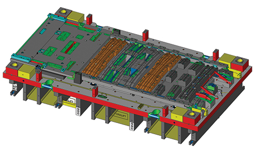
Software Lets Centerline Engineering Dial in Early During Die Design
As high-strength steel increased its presence in automotive applications during the early 2000s, Centerline Engineering sought better ways to assess the tough and tricky material’s formability. That led to the company’s initial purchase of eta/Dynaform forming-simulation software from Engineering Technology Associates, Inc. (ETA) in 2003, and it’s been employing the software ever since.
Comstock Park, MI-based Centerline Engineering, formed in 2000 and now counting about 100 employees, designs, builds, tries out and repairs progressive, transfer and line dies for automotive and appliance stampers. To do that, it fills 68,000 sq. ft. of manufacturing space with eight tryout presses, including a new 2500-ton large-bed press from Eagle Press; CNC five-axis, vertical and horizontal mills; wire EDMs; and more.
Keeping that machinery running productively, and keeping customers happy with on-time delivery of tooling that produces quality parts, begins with inhouse engineering expertise backed by design solutions such as Dynaform, according to Travis McCall, a Centerline simulation engineer.
“We initially used Dynaform to check the feasibility and help us deal with high-strength steel,” McCall states. “We needed as much information as possible before we moved into the actual die design. Whether assessing springback or other issues, checking feasibility up front allowed us to achieve a better end result.”
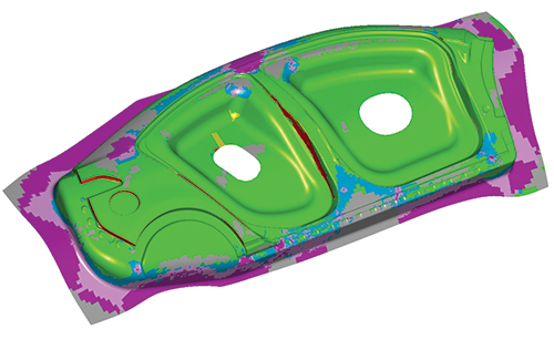 |
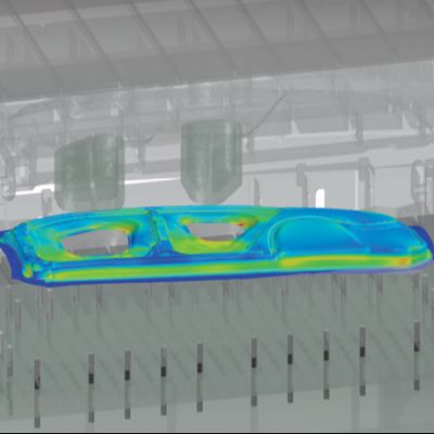
| Centerline Engineering employs Dynaform forming-simulation software to assess formability and more, starting early on during the quoting process. Accuracy in its simulation software prevents costly rework and other problems during die build and tryout, according to company officials. |
Currently using Dynaform Version 5.9.4, the company is set to employ the latest package, Version 6.0, featuring a streamlined interface and optimized algorithms. Modules include Blank Size Engineering for estimating blank size and nesting as well as predicting predict thinning and thickening, and generating a forming-limit diagram; Formability Simulation for rapid development and validation of single-station and progressive-die designs; Die Evaluation to support and analyze CAD-based tooling and engineering designs; Die System Analysis to predict stamping-related concerns within the die production line, as well as analyze scrap removal, die structural integrity and sheet metal handling; Optimization Platform to optimize design; and more.
“Sending a die to the press with the trim line developed and springback compensated using the software can decrease the overall project timing,” McCall says, describing the efficiencies and accuracy that the software brings to the design and build process. “With our newer 2500-ton tryout press, the ability to be accurate, especially on larger dies, allows us to meet the limited timeframe available for that press, as it is one of the few presses inhouse that can handle our largest die-design programs.”
Today, with five seats of Dynaform, Centerline uses the software “right from the get-go,” according to McCall, starting with quoting and continuing through the design process.
“We use it to give our customers the best results from the start of a program to its finish,” he says. “During quoting, we may use it to accurately estimate blank size and nesting, important in saving on material usage and cost. The software lets us know where we can hold the blanks using the least amount of material. We can set the pitch and rotate a blank to optimize pitch (the distance between adjacent blanks). Gaining that little bit of extra material on the pitch is huge—enough to hold the blank but not wasting material.”
The software also checks the formability of drawn parts based on bead locations and pad pressure—another big plus, according to McCall. And, blank development in Dynaform represents one more advantage for Centerline.
“The Trim Line Development module allows us to develop a blank, accurately and in tolerance,” McCall explains. “It provides a very close approximation not only on the blank end but also on the secondary trim for any forming performed afterward. We pretty much just input information and input what we want at the end, and the module cycles through and provides an accurate solution. Again, we perform all of this up front to save time and costs, and eliminate problems later on.”
Report generation represents one more advantage to employing Dynaform, automatic generation of simulation reports, coming in Version 6.0, makes McCall and Centerline even bigger fans.
“The automated simulation reports will save us a ton of time,” McCall says. “None of us want to sit there making PowerPoint presentations all day, and continuously updating reports with every change. Automated reporting will take care of that and free us to do design work.”
The Dynaform software ties in handily with the 17 seats of Catia 3D CAD design software employed by Centerline, reports McCall, who also notes that ETA responds immediately to assistance requests and with training and other support.
With the software’s many capabilities, backed by the support network Centerline performs the above-mentioned actions successfully no matter the type of material slated for production in the dies, reports McCall.
“We build dies for some pretty big parts and a variety of part materials,” he says. “This includes dual-layer material, and the software handles it. For example, we work with dimpled aluminum—two layers of aluminum with insulation between. Simulation involving dimpled aluminum is difficult and takes a bit longer, but when we physically try out the die, the parts look exactly like the simulations.
“We’ll always have unique variables and some challenges that are tougher than others,” McCall concludes, “but Dynaform provides accuracy up front, and that saves us time down the line.”
Job-Tracking, Quoting and Management Software a Perfect Fit for Job Shop
Accurate cost estimating and job tracking are critical in running a successful and profitable business. Estimating too high delivers fewer jobs, while estimating too low shrinks profits. And, losing track of an invoice, or forgetting to invoice a customer, affects the bottom line. The key to success: Get it right every time.
In 2016, Tombigbee Tooling, Inc. (TTI), Manatachie, MS, while searching for a job-tracking and quoting solution to turn quoting into a seamless, time-saving and accurate process, turned to TSTracker and Estimator ERP software from TST Tooling Software, LLC.Selling TTI’s owners, DeWayne and Debbie Thornton, on the software was its ability to provide the consistency and accuracy necessary to optimize profitability.
Established 30 years ago as Smith Tool & Die Co., TTI started out machining fixtures, stamping dies and more for local industries. Today, in an expanded 22,000-sq.-ft. operation, the company and its 43 employees across two shifts routinely design and manufacture progressive, manual-transfer and automated-transfer dies.
In incorporating new software, the Thorntons required of it three things: 1. Guarantee the flow of work through the shop with minimal disruption to the current process; 2. Allow managers to oversee everything at the touch of a button; and 3. Quote jobs accurately.
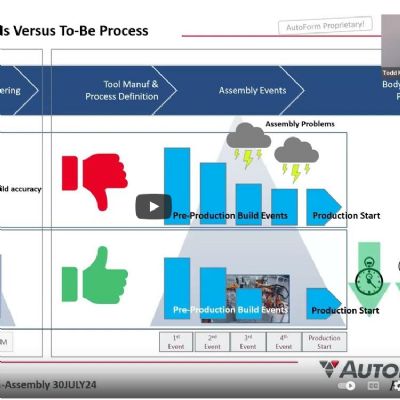
TST Tooling Software provided this video of customer testimonials.
TTI previously employed a web-based, generic job-tracking and management system, but that didn’t fit into the company’s desire for a customizable system that could serve as a platform to handle future management efforts, improvements and expansions.
Because TTI benefits from using VISI software to build tools, the company also would benefit by employing TSTracker. That’s because TST Tooling Software Technology, developer of TSTracker, also sells and supports VISI CAD/CAM in the United States. In addition, TSTracker and Estimator has the ability to communicate with VISI, thus providing an integrated solution for estimating and design.
Today, with the software in place, TTI seamlessly tracks jobs from start to finish. Using Estimator, the company can quote all aspects of a die build, from materials and components to labor. Within TSTracker resides a full database history of TTI quotes and jobs that can be referenced easily when generating future quotes. Bills of materials (BOMs) from all jobs can be imported from any CAD system, which can be used to create RFQs and purchase orders for materials and components. Vendor purchase orders can even be exported to QuickBooks.
As to implementation, TST performed onsite installation of TSTracker and Estimator and associated training, a process that only took three days, according to TTI officials. And, TST showed TTI departments how to use the system to its advantage. Accounting learned how to export reports from TSTracker to QuickBooks. CAD designers learned how to import BOMs easily from VISI, and TTI’s quoting department reportedly picked up the ins and outs of TSTracker in only a couple of hours. Typically, everyone in the company can learn and perform the various processes within a few days, according to TST officials, with TST’s support line available to address issues and answer questions.
Beyond only tool design and build, the administration, tracking and paperwork comprise other key functions of a job shop. The multi-user TSTracker ERP software provides for complete histories, inspection tracking, employee accountability, password control, production status and more at a glance.
Debug Dies on the Computer Screen
Metalstamp, Inc., Minooka, IL, specializes in stamping lead frames for the automotive industry, but recently also has begun stamping HSLA brackets for sunroofs and for other automotive applications. The company employs 20 presses and features four servo-driven presses, one of those a new 330-ton Aida press used to stamp the new brackets. Metalstamp designs 40 to 50 new dies each year, including about 20 progressive dies, with trim dies as the balance. As sales have grown, the company manages to keep the number of toolroom personnel constant. A big part of accomplishing this: moving most of the die tryout and debug operations from the tryout press out on the plant floor to the computer screen in the office. This ability fits perfectly with Metalstamp’s progressive nature and willingness to keep up with technology.
After a dozen years using a 2D die design add-on for AutoCAD, Metalstamp purchased SolidWorks-based Logopress3 in 2011. At that time, Ben Hutchinson, currently Metalstamp operations manager, and a colleague worked as die designers. Months later, Joel Martin began performing die design at the company and completed his first design using only SolidWorks.
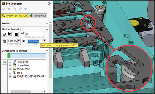
Die Debugger’s Motion Simulation tab in Logopress3 allows the user to see the die running in a virtual press (including the strip lifting and advancing), and motion can be paused at any point in the 360-deg. press cycle.
“I realized after that first die design that something was missing.” says Martin.
A short time later, Metalstamp added another Logopress3 seat for Martin. In using Logopress3, Martin appreciates all of the standard catalog components included in the software, and the amount of work done automatically when adding the components. The software not only adds a component, but also creates a hole pattern when requested, cuts all the holes for the component, adds the correct ordering information to the bill of materials and adds attributes to all of the holes that will appear when a hole table is inserted in the 2D detail drawing—all automatically.
“With today’s designs, we make them very complete, as the tool already is built on the computer,” says Martin. “When adding a cutting punch, the software includes clearance in each of the plates at the same time. And the fact that they are linked together makes a big difference. Going back and making a change to the 3D model changes everything—including whatever 2D drawings had been created. The tool and die makers can produce the die exactly as I designed it, and the die is going to work—a big difference as compared to how we used to do it.”
Adds Hutchinson: “One reason for less mistakes when using SolidWorks and Logopress3 is that it forces you to be more thorough than when using 2D die design software. You must fully define sketches as you create the design.”
Designing with 2D CAD was speedy partly due to users not needing to create nearly as much information as when using 3D parametric design, according to Ray Proeber, president of Accurate Die Design Software, noting that running the die in a virtual press on the computer screen using Logopress3 requires 3D die design data.
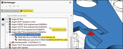
The Logopress3 Interference list tab shows each interference found as the die is running. In this case, the selected interference is the stretch web portion of the skeleton/carrier colliding with the pilot lifter as the strip is feeding.
“I’m not sure if the designs have gotten much faster, but for sure they are much more complete,” says Hutchison.
More complete designs flow more quickly through the shop, and, of course, design cost represents only a fraction of build cost, according to Proeber.
Metalstamp has employed Logopress3 for virtual tryout on the computer screen for several years. “Several of our dies have fit together without one problem, and parts come out nearly perfectly the first time in the press,” says Martin.
Among the new Logopress3 enhancements enjoyed by Martin: the tryout portion of the software, renamed as Die Debugger, along with online how-to videos and live online screen-sharing meetings included in the technical support for the product. Most of the setup for Die Debugger is not performed at the end of the design, but takes place on an as-needed basis during creation of individual die stations. When using 2D CAD software, or even 3D die design software without a tool such as the Die Debugger feature, Martin notes that the motion of the die’s various stations must be accounted for one way or another during design of the die in order to understand the travels of the various components.
Hutchinson likes the fact that 2D detail drawings can be produced with Logopress3 in a matter of minutes, but Metalstamp typically makes very few detail drawings and doesn’t create section views. Because the toolmakers have access to eDrawings, they easily can access the model and its individual components as they create parts for the die. And, the company’s CAM software uses the actual 3D models for the programming as opposed to using 2D drawings. “For 2D drawings that we do create, when we make changes to the 3D model, the software updates all of the previously made drawings automatically,” says Hutchinson, describing what he sees as the most noticeable benefits over designing in 2D CAD from a drawings standpoint. “2D CAD design requires going back and manually changing every drawing.”
Look for more case histories, including those from AutoForm and T-Sim Solutions, in the May issue of MetalForming. MF
View Glossary of Metalforming Terms
See also: ETA (Engineering Technology Associates, Inc.), Accurate Die Design Software, Inc., LOGOPRESS, 3D Systems, TST Tooling Software Technology, LLC
Technologies: Software
 Webinar