Piyush Bubna Piyush Bubna
Manager
Michael Humbert Michael Humbert
Staff Engineer

3D Metal Printing of Automotive Stamping Dies

May 1, 2016
0
Comments


In a project for the Advanced Research Projects Agency—Energy (ARPA-E), conducted during the first nine months of 2015, Ricardo, Inc. partnered with United Technologies Research Center (UTRC) to develop a detailed cost model for 10 key automotive components (chassis, powertrain, controls, etc.). The project, titled Reducing Automotive CAPEX Entry Barriers through Design, Manufacturing and Materials, analyzed the investment barriers for lower-volume production. Amongst various findings were opportunities to use 3D printing to reduce the necessary investment in tooling.

No Secret: Tooling Can be an Investment Barrier

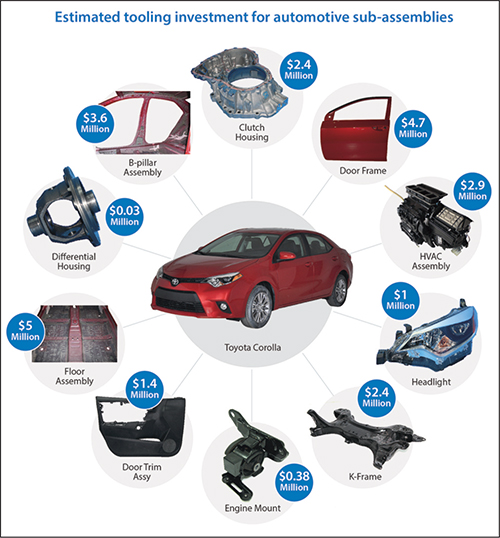
Leveraging its manufacturing expertise and newly developed manufacturing cost model, the Ricardo team studied capital costs associated with the conventional manufacturing of 10 subassemblies from the Toyota Corolla.

Passenger vehicles and commercial trucks incorporate several metal components in the body-in-white, closures and other areas of the vehicle, often requiring enormous capital investment in tooling. The cost of a die set can vary from a few thousand to more than $1 million, depending on die size, part complexity, and required die durability and life. Due to these limitations, major automotive manufacturers produce very similar, if not virtually identical, vehicles at very large volumes. This practice limits potential customization and acts as a barrier to entry for new companies or for new production techniques.

Companies trying to customize their products or bring new technology to market typically lack sufficient opportunities to achieve economies of scale. Low-volume demand for aftermarket parts also suffers from the same limitations. These stakeholders can benefit from alternative methods to affordably manufacture vehicles at initially lower volumes, and reduce the time required to provide new products to consumers.

To study these challenges, Ricardo developed a manufacturing-cost model and database that enables users to estimate production costs and required investments for a large variety of components at different production volumes. The cost model determines bottom-up costs for forming of individual parts, as well as their assembly into components. It can analyze key business drivers such as tooling investment, equipment cost, process time, materials, scrap, automation, labor, supply-chain impact and factory overhead.

To develop a cost-effective and rapid process to print dies, the Ricardo-UTRC team opted to use preforms—starting plates or extrusions—and then use the WAAM process to 3D-print all of the necessary features onto the preforms.
The model is supported by an extensive database of information on a range of materials, manufacturing processes, equipment and a common set of factory operating parameters. All of this allows the comparison of traditional manufacturing techniques to emerging technologies. The cost model and approach has been vetted by industry experts representing OEMs, suppliers, academia, consultants and national laboratories.

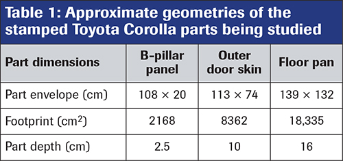
Leveraging its expertise and the manufacturing-cost model, Ricardo studied the costs associated with the conventional manufacture of 10 subassemblies for the Toyota Corolla, representative of a traditional high-volume passenger vehicle. The cost analysis shows that, for all of the analyzed components, production costs start to become prohibitive below an annual volume of 50,000 units. The root cause is the relatively large capital investment needed for dies, fixtures and other tooling. For this reason, manufacturers must try to achieve economies of scale by sharing platforms for different vehicle models, and using common components.

Cost Reduction via 3D Printing

Traditionally, stamping or drawing dies for high-volume production are expensive. Machined from hard material such as tool steel, the dies undergo heattreatment for surface hardening, and polishing to achieve a high-quality surface finish. Adopting less-durable and softer tooling and reducing automation in the processing line represent some of the options available to reduce the required capital investment and overall production costs. But, these options can inhibit the ability to achieve the desired dimensional accuracy and surface finish.

As Ricardo and UTRC collaborated to explore the economic feasibility of innovative production techniques, they took a look at the use of additive manufacturing (AM) to fabricate stamping dies. Among the AM techniques considered were laser and electron-beam powder-bed processes, which tend to provide the best geometric accuracy; and lower-cost welding processes that can more-rapidly deposit material, but do so with limited geometric accuracy. Researchers ultimately decided that wire-arc additive manufacturing (WAAM) offered the ideal solution for developing stamping dies that do not require fine features.

WAAM builds components layer by layer by depositing molten metal delivered by weld wire. The process uses six-axis robots in conjunction with a specialized cold-metal-transfer (CMT) welding system to produce a fully dense deposit. The process, which provides well-controlled heating and rapid cooling, can lead to hard deposits with limited warping of the final parts in the absence of extensive post treatment.

Additionally, the technique uses a wire feedstock that enables the use of a shielding gas, rather than the highly controlled oxygen-scrubbed environment required when using high-surface-area powders. Also, since drawing a wire is less energy intensive than atomization of material to produce well-controlled powder-particle size, the WAAM technique also is energy friendly and cost effective from a feedstock standpoint.

Printing Off of Preforms

To develop a cost-effective and rapid process to print dies, the Ricardo-UTRC team opted to use preforms—starting plates or extrusions—and then apply the WAAM process to 3D-print all of the necessary features onto the preforms. This saves significant time and money compared to 3D printing a die from scratch. The starting plates have a larger cross-section than the 3D-printing area in order to handle the stresses at the edge of the die during stamping. Further, they need sufficient thickness to handle the forces across the part.

To meet the required die dimensional tolerances, excess weld metal is deposited and then finish-machined. Researchers estimate that this excess metal should be 15 percent of the total volume needed—likely to be overly conservative for large dies with relatively flat surface geometries, but useful for determining the costs associated with AM of dies.

Further, in evaluating the cost of finish-machining the 3D-printed dies, it is assumed that the first 85 percent of the excess material can be removed quickly and at relatively low cost, and the final 15 percent finish-machined at a higher cost. Cost estimating also accounts for surface heattreatment and manual polishing of die surfaces.

A Case Study

Ricardo and UTRC estimated the cost savings realized by 3D printing dies for three Toyota Corolla parts (Table 1): a B-pillar panel, door outer skin and main floor pan. Manufacturing the parts requires die sets for blanking, drawing and a trim/pierce operation; the cost comparison focused on the draw die set for each component.

The B-pillar panel is the smallest part, and has the smallest draw depth. The floor pan is the largest part, in crosssection and in draw depth. Table 2 presents the costs and the time required to produce the die sets via WAAM, including finish machining, polishing and heattreatment.

The results of this economic assessment show that the cost benefit of 3D printing the draw die depends on the part size and depth of draw. The draw die for the B-pillar panel requires less material deposition due to the smaller part size and relatively shallow draw depth, so it’s less expensive to manufacture. However, as draw depth increases the cost savings achieved by using additive manufacturing diminish, due to the relatively slow deposition rate from the WAAM process.

The substantial difference in additive-process cycle time to 3D-print the die sets for the B-pillar and floor pan (Table 2) reflects the difference in the amount of material deposition required. Further, since the cost of the weld wire exceeds that of the base metal, material cost becomes significant as draw depth and part size increases. A common trend in cost estimates for the three die sets is that finish machining and polishing account for the majority of the manufacturing cost. Therefore, tooling can be made less expensively with 3D printing when parts do not require a high surface finish.

Advancing 3D-Printed Dies

The benefits of this concept extend beyond the realm of automotive manufacturing and apply across any metal-stamping application. The WAAM process can offer an economical advantage when producing die sets for parts with relatively shallow draw depths. However, as part complexity grows, and for dies that require cooling channels (for hot stamping, for example), a powder-bed AM process may prove more advantageous.

While the slow deposition rate and high investment cost of a powder-bed system are prohibitive, the better geometric accuracy from powder-bed processes can enable the placement of conformal cooling channels. These can improve temperature distribution along the part surface and also substantially enhance cooling. MF

Industry-Related Terms: Blanking, Case, Center, Die, Draw, Drawing, Edge, Forming, LASER, Layer, Model, Polishing, Scale, Scrap, Shielding Gas, Surface, Thickness
View Glossary of Metalforming Terms

Technologies: Additive Manufacturing, Tooling

Comments

Must be logged in to post a comment.
There are no comments posted.

Subscribe to the Newsletter

Start receiving newsletters.