John Kemp John Kemp
Applications & Training Mgr.

Crowning Achievements Deliver Press Brake Accuracy and Process Efficiency

January 1, 2010
0
Comments


State-of-the-art press brakes all offer

Press Brake Accuracy and Process Efficiency
high accuracy and repeatability; what separates high-end machines from the rest of the pack is the ability to adjust to the changing properties of the workpiece material. Even with the most accurate and repeatable machine in the world, if its crowning system cannot adapt as material properties change from part to part, there is no to guarantee accurate, repeatable forming results.

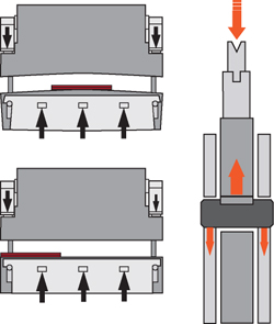
Crowning—the method by which press brakes compensate for deflections in the upper beam and lower bed when pressure is applied—occurs by different methods depending on the make and model of press brake. And while any type of crowning system is better than none at all, fabricators must carefully consider the effectiveness of the crowning system when comparing and contrasting the press-brake models on the market.

Any time pressure is applied to the machine, deflection occurs and is directly related to the amount of pressure applied, where it is applied and over what area. For a crowning system to be effective, it not only must account for all of these variables, but also must be able to adjust for them on the fly, without operator input.

Springback Problem?

While you may believe that you have a springback problem, it’s more likely you have a crowning problem being attributed to springback. According to Hooke’s Law, springback is proportional to force, which is proportional to material tensile strength. The reason a fabricator may experience a large variation in bend angle from one workpiece to another—when the material’s tensile strength changes—has more to do with the pressure required to complete the bend than the actual amount of springback.

Consider, for example, bending a section of ¼-in. plate to a 90-deg. angle in a press brake. Assuming 3 deg. of springback (typical for steel) and a tensile-strength variation of 10 percent; the amount of springback, therefore, also will change by 10 percent. This results in an angle variation of only ±0.3 deg. What causes fabricators to experience angle variations much larger than this? The answer: insufficient crowning.

When tensile strength increases by 10 percent, the press brake must apply 10 percent more force to bend the part. This means that the press brake needs an additional 10 percent crowning and 10 percent added frame-deflection compensation. While most machines will compensate for frame deflection in process, very few will change the crowning as the press brake operates. In fact, it would be impossible to change the crowning on any type of mechanical crowning system in process, since these types of presses are not adjustable under load. In these cases, insufficient crowning results in an open angle, often attributed to springback.

Dynamic Crowning the Noble Solution

With a dynamic crowning system rather than a mechanical system, as the pressure changes so does the amount of crowning. In-process crowning compensation minimizes springback variation.

Behaving similarly to changes in material properties, changes in sheet thickness also will affect bend-angle repeatability, and dynamic crowning helps here, too. As in the springback case described above, when thickness changes so does the required pressure from the press-brake ram. A different amount of ram and bed deflection results and, unless the press brake adequately compensates, a different bend angle is formed. A 10-percent change in material thickness requires a 20-percent change in pressure, which demands a 20-percent change in crowning.

While many press brakes on the market today offer some sort of thickness measurement and compensation, the question that fabricators should ask: How does the press brake adapt its crowning to the change in pressure, which the change in thickness required? Without an adaptive crowning system, it is impossible to adjust the crowning to the changing pressure.

Crowning Systems: A Regal Past

In the late 1970s and early 1980s, two decidedly different crowning systems were introduced into the market. One comprises a mechanical solution using opposing wedges, each with a different slope angle. A hand crank or CNC motor shifts all of the top wedges lengthwise in reference to the bottom wedges, creating a curve with which the deflection in the press brake can be compensated for automatically. However, as previously noted, this crowning method cannot be adjusted while under load. A fabricator must apply the crown before bending (pre-crown), and cannot adjust the crown if tonnage changes.

The second crowning method, introduced in 1982, employs a hydraulic system.
Three-piece press-brake bed construction
A three-piece press-brake bed construction and short-stroke cylinders applies pressure during the bend stroke to compensate for machine deflection under load. Dynamic crowning systems automatically adapt to changing bending pressures on the fly, caused by variations in material properties or sheet thickness.
By using a three-piece bed construction and short-stroke cylinders (see illustration), the system applies pressure to the cylinders during the bend stroke to compensate for machine deflection. By 1992, this capability was expanded to include automatically adapting to changing bending pressures on the fly, referred to as dynamic crowning.

For a crowning system to be truly adaptive, it must compensate for changing pressure, for workpiece position on the press-brake bed, and for bend length. Many factors affect bending pressure, including material tensile strength, grain direction, thickness and hardness. In order for a crowning system to be effective, it must be able to adjust as these parameters change. Crowning is required because of machine deflection; machine deflection directly relates to bending pressure. If the pressure changes, so does the deflection. Shouldn’t the crowning as well?

While this is easily accomplished with a hydraulic crowning system, it simply is not possible with a mechanical wedge system. The best a fabricator can hope for is that the process variables do not change and that actual tonnage does not vary from the programmed tonnage.

Adjusting for Off-Center Loading

Many press brakes struggle to form straight parts as the fabricator moves the workpiece a from the center of the machine. Most solve this with some type of automatic ram-tilt feature included with the press brake. However, the root cause of the phenomenon is an inadequate crowning system. For example, assume that the actual pressure used for a job is the pressure programmed in, but the fabricator decides to bend toward the left side of the machine instead of in the middle. Moving closer to the side frame and hydraulic cylinder results in significantly less deflection in the upper beam and bed than would be present had the workpiece been centered in the machine. Without adjusting the crowning system, a different bend angle will result on one end of the part than on the other.

To avoid this inconsistent bend angle along the part, a dynamic crowning system will independently measure the pressure on each side of the press brake, calculate the bending location and adjust the multiple crowning cylinders accordingly, all on the fly and invisible to the operator.

Hear Ye, Hear Ye—Crowning Helps with Short Parts and Long

“Crowning is only required on long parts,” some might say. This, however, simply is not true. If you apply 50 tons of force over a 10-ft. bend length, much less deflection of the upper beam and bed results than if you were to apply 50 tons over a 1-ft. area located in the center of the machine. Therefore, since more deflection of the upper and lower beam results when applying pressure only to the center of the press brake, you need much more crowning to achieve the same relative bottom-dead-center position.

While it is true that a simple angle correction can be made to achieve the target angle in the middle of the machine, why should you have to correct for errors in your crowning system? Shouldn’t the machine be able to compensate for its own deflections? Unfortunately, most do not. The crowning calculation for most machines is based strictly on tonnage—program 50 tons, you get 50 tons worth of crowning. Not so with dynamic crowning systems, as fabricators using them can attest to a reduction or elimination of setup pieces; avoiding the need to check parts within a batch run; and less operator training.

In fact, the entire crowning system is completely invisible to the operator. With a dynamic crowning system, fabricators can expect to reduce labor time and required skill level, slash inventory costs, reduce lead time, minimize scrap, increase productivity and improve quality. MF

Industry-Related Terms: Bed, Bending, Case, Center, CNC, Form, Forming, Grain Direction, Lead Time, Model, Plate, Ram, Run, Scrap, Stroke, Tensile Strength, Thickness
View Glossary of Metalforming Terms


See also: Bystronic Inc.

Technologies: Bending

Comments

Must be logged in to post a comment.
There are no comments posted.

Subscribe to the Newsletter

Start receiving newsletters.