How it Works
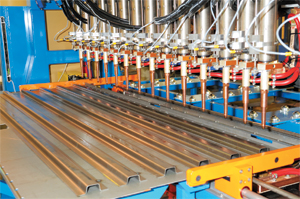
To run the machine, an operator loads a pre-tacked panel onto the machine and positions it against the left-hand gauge-bar assembly and underneath a series of laser-dot indicators. These indicators help the operator align the material to ensure proper weld placement along the stiffener flanges.
The operator then initiates the weld sequence. The right-hand gauge bar extends and forces the panel against the opposing gauge bar. With the panel locked into weld position, the toggle table extends to bring the 16 lower electrodes up. The upper welding guns
then extend downward and the first series of 16 welds are completed. The guns retract, the toggle table drops, the gauge bars shift the panel and the sequence repeats.
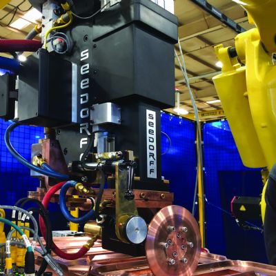
To fabricate a prison-door panel (shown), Chief Industries’ new automated resistance-welding machines features 16 opposing sets of welding guns to spot-weld mild-steel top-hat-shaped stiffeners to a galvanneal sheet. Bottom electrodes mount on a toggle table that lifts the electrodes into welding position as the top electrodes index downward. With a weld cycle completed, the toggle table retracts to allow the panel to automatically index to the next weld position without dragging over the bottom electrodes.
The setup uses 1.25-in.-dia. zirconium-copper electrodes (preferred for welding galvanneal and other coated materials, to avoid electrode sticking)—Tuffaloy TA-25CZ male caps on top and a flat-face lower electrode. Reduced weld heat and power, combined with the ability of the toggle table to prevent electrode marring during indexing of the assembly, have improved electrode life between dressings by 20 percent, says Peters.
Turn Down the Power
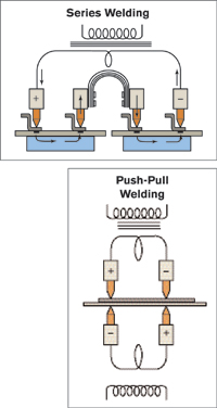
Along with its automation capabilities, the machine’s push-pull circuitry is a big hit at Chief Industries. T. J. Snow engineers designed each of the machine’s eight push-pull circuits, which run along the width of the machine, to include four weld guns and two transformers. The machine’s upper crown and its lower knee each hold a bank of eight transformers to power the circuits. This differs considerably from the previous machine’s series-welding circuitry, which used only four huge transformers mounted to the upper crown, Each transformer had to generate enough power to complete a set of four welds per cycle.
“We really had to crank up the power to pull the nuggets and form the spot welds,” says Peters. “This created quite a divot at each weld location. Now, the push-pull setup provides better weld control and nicer-looking nuggets, with much less heat input, so the resulting divots are barely visible.
“Yes, we have twice as many transformers as we used to, but the payback is definitely there,” Peters adds. “Weld quality is improved, overall power consumption is down, and we have practically eliminated the added, wasteful process of filling each weld divot with Bondo and then grinding and polishing each repair.” MF
View Glossary of Metalforming Terms
See also: T. J. Snow Company
Technologies: Welding and Joining