Hirsch: The most probable cause of power loss is in the welding transformer’s secondary copper. While copper is an excellent conductor, the places where the copper components of the secondary bolt together can oxidize over time. This oxide has a much higher electrical resistance than the bare copper. Each bolted joint drops some voltage, reducing the voltage available for welding and causing the reduction in heat.
The solution: Remove and inspect all of the bolted joints, starting at the welding transformer’s front copper pads (Fig. 1). If they are just slightly discolored and not showing large areas of melting or high spots, clean them with a 3M Scotch-Brite pad—the red pads work best for this. Never use emery cloth or other abrasives as they cause grooves in the surface that reduce the available conducting areas.
With the surfaces clean, apply a coating of silver-plating powder (such as Cool-Amp) on both sides of each joint. To use, dip a soft cloth into clean water and then dip into the powder. Rub the powder across the surface several times, let the part set for at least 2 min., and then buff with a soft cloth. Repeat layers until achieving a dull silver color.
If the surfaces show arc points that are not flat, machine them flat. Only do this if more than 25 percent of the surface is bad. Then use the silver-coating process when finished.
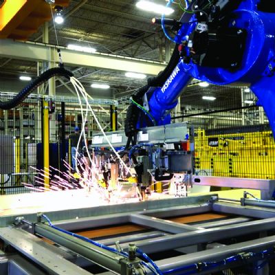
Also check the condition of the shunts. On most welding machines, the secondary current is conducted from the transformer to the upper moving part of the machine through a stack of flexible thin copper sheets called a laminated shunt (Fig. 2). Over years of use, these pieces of copper break off near the fastening points, which reduces the number of sheets left for conducting the welding current. If more than five percent of the sheets have broken off, replace the shunts. They are not expensive, and an RW-equipment supplier can produce an exact, and probably improved, laminated shunt.
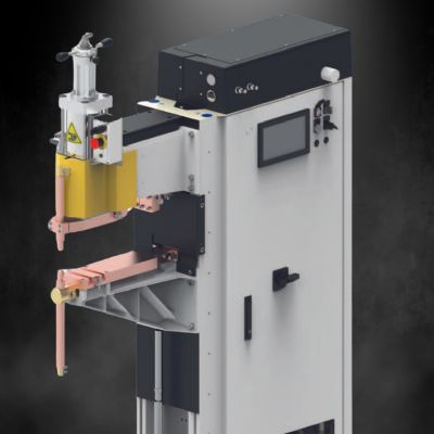
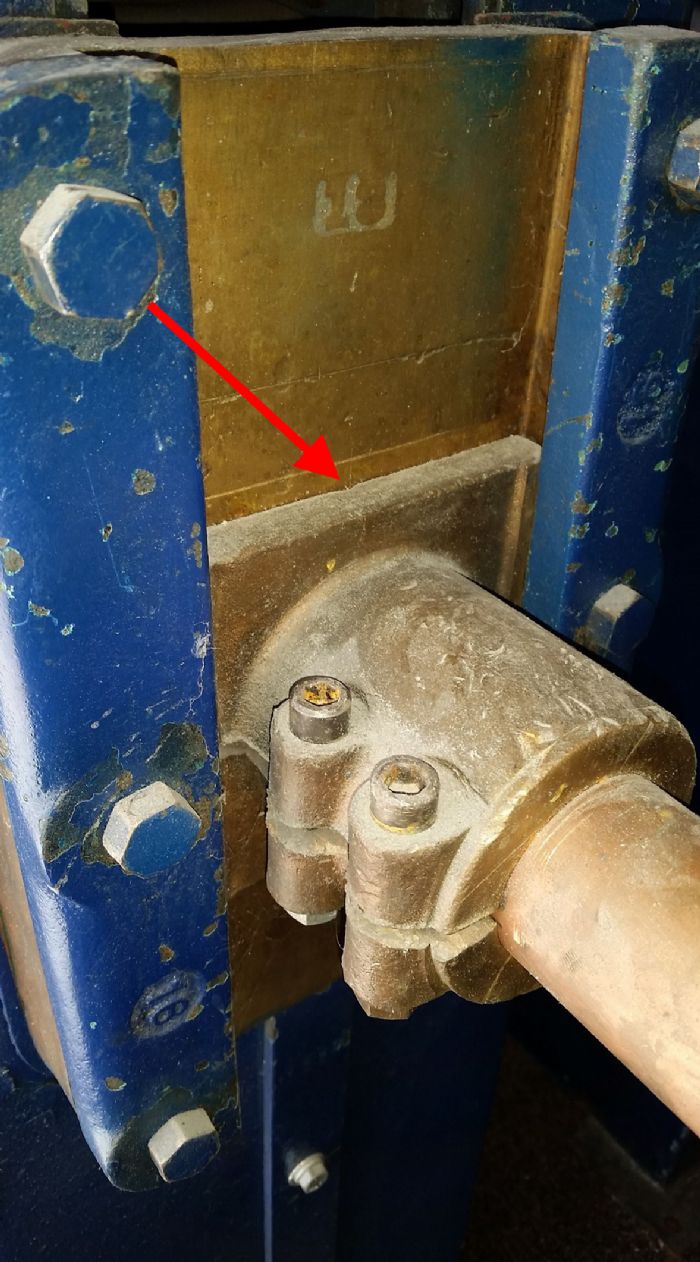
 Finally, check the areas where the electrode holders attach to the welding machine’s arms (Fig. 3). It is not unusual to see a holder that has been smashed with a hammer during “adjustment,” with that portion of rough surface pushed lower into the arm to conduct electricity. Remove the electrode holders and check for smooth, clean surfaces. If the holders are beat up, replace them. New ones are inexpensive, and you will gain power while eliminating water leakage where the electrode is installed.
After cleaning and reassembly, the welding machine likely will produce 20-percent-or-more power with the same heat settings.
Q: We have only one RW machine in our plant, originally purchased to weld 12-gauge channels. We recently brought in a new project requiring welding of 22-gauge steel panels and drawers, and the machine is too large. We have to set the weld heat at about 30 percent to create welds that do not expel metal out into the aisles. However, this low heat setting creates a very small process window for creating good welds—just a small change in electrode force or weld heat produces welds that snap off without making good nuggets. What can we do?
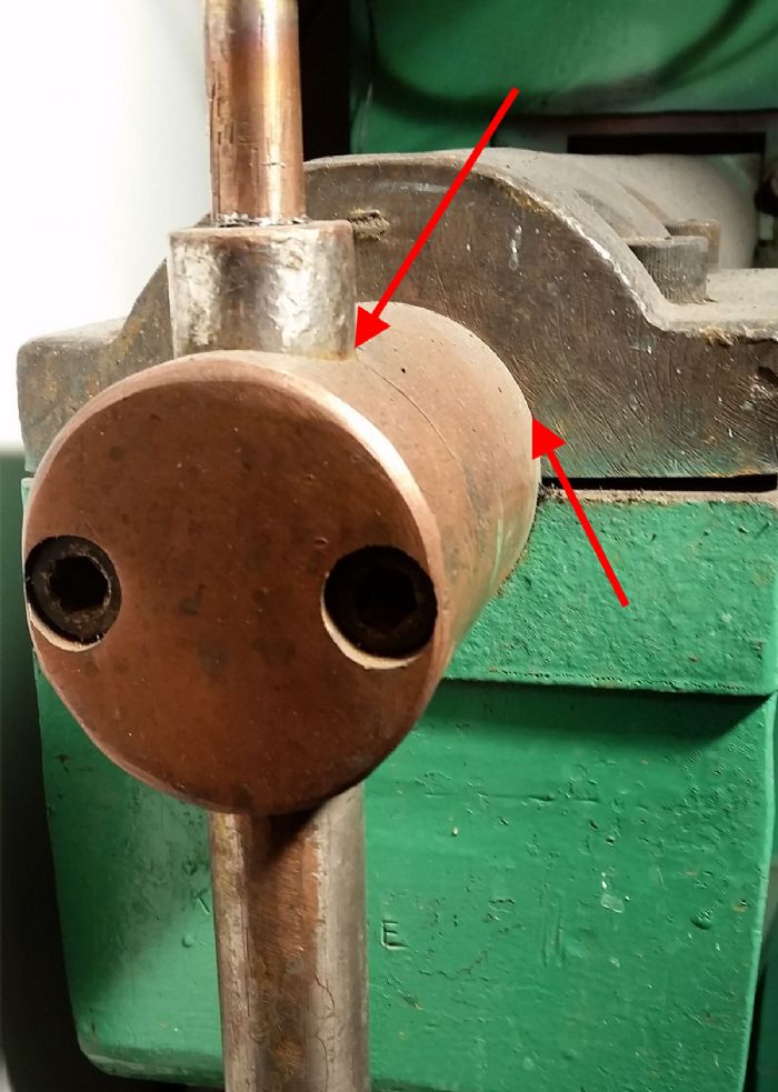
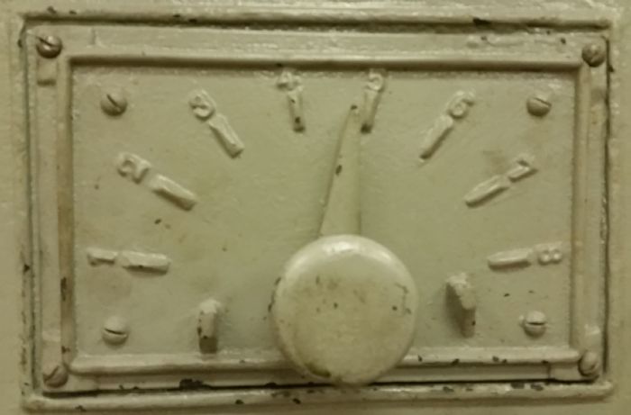 Hirsch: Unfortunately, the “one-size-fits-all” concept does not work well with RW machines. But you can try a few things. First, look for a large tap-switch handle, either on the side of the machine or mounted to the welding transformer itself, to adjust the secondary voltage of the welding transformer. Setting the tap switch to a lower number will reduce the welding current and should allow you to make better welds on thinner sheet metal; keep the weld-heat percentage setting no lower than 60 percent. To weld thicker sheet metal requiring a weld-heat percentage greater than 90 percent, turn the tap switch to a higher number (Fig. 4).
Unfortunately, some newer RW machines do not have tap switches. In this case, you might be able to reduce the secondary voltage by locating the internal terminals in the back wiring compartment of the welding transformer. First, turn off the power to the welding machine and lock out the disconnect switch. Then remove the back plate from the welding transformer and look for large studs inside, likely marked with numbers—the lower the number the lower the weld heat. Unbolt the wire attached to a higher-number stud and bolt it to a stud with a lower number.
If the welding transformer does not have these studs and has only one heat setting, the only other choice is to operate the welding machine on a lower line voltage. If the machine is rated at 440-460 V, connect it to a 220-V line (if you have one large enough). The machine now will generate about one-half the secondary current, allowing you to set the control to a much higher welding-heat percentage to provide a more robust and stable welding process. MF
See also: Unitrol Electronics Inc
Technologies: Welding and Joining


 Q: Our company resistance welds a lot of weld nuts onto channels, and we’ve had trouble obtaining good weld strength—until our welding foreman increased weld time. Now we have acceptable weld strength but our quality-control department says that the thread on the weld nuts will not pass the go/no-go test. What are we doing wrong?
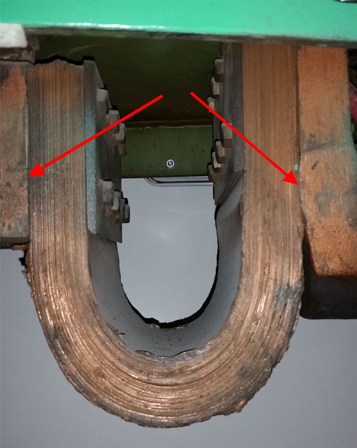 Low electrode force also can cause a change in thread pitch. The contact point under the electrodes will overheat and place the metal in a plastic state. While it sounds counterintuitive, increasing the force can reduce the compression of the nut if weld time is reduced and weld heat increased.