


Redrawing and Ironing Cylindrical Shells, Part 2
January 29, 2020Comments
Last month, we examined the differences between cylindrical redrawing and ironing, and guidelines for choosing diameter and thickness reduction percentages. This month we turn our attention to punch-nose geometry and draw-sleeve design.
Punch-Nose Geometry
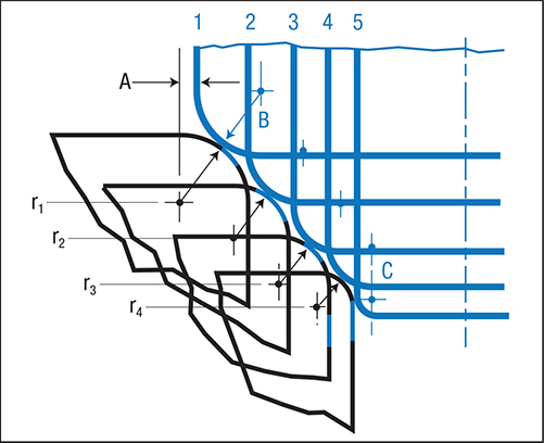 |
| Fig. 1—Relationship between shell radii (blue) and die radii (black). Adapted from Die Design Handbook, 3rd Ed. |
In general, the punch-nose radius for drawing will be four to 10 times the material thickness in order to prevent thinning in the bottom of the shell. Very thin materials require much larger radii, as much as 20 times material thickness.
When employed in the first draw operation, sharp radii may cause thinning in the wall of successive redrawing operations, showing as a line or depression. This impression moves higher up the wall with each additional reduction.
A specific relationship between the redraw shell radius and the die-entry radius exists to minimize metal thinning in each redraw operation, as shown in Fig. 1.
- The center of each redraw radius, approximately 0.125 in. outside of the previous cup wall (point A), depends on material thickness and the diameter of the preceding shell. The objective: Have the outside radius of the shell contact the die entry radius at approximately 45 deg. of tangency.
- The center on the punch-nose radius should be slightly inside of the following shell diameter (point B).
- The center of the punch-nose radius for the final two operations, on about the same line (point C), maintains the flat on the bottom of the shell.
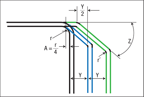 |
| Fig. 2—Angular-corner relationships. Adapted from Die Design Handbook, 3rd Ed. |
The angled corner profiles for the redrawing operations are developed from the finished shell, as shown in Fig. 2.
- The angle in the bottom of the preceding shell should start at a point equal to approximately one-fourth of the bottom radius in the finished shell (A).
- Angles for addition redraws should start midway between the draw reduction diameter (Y) of the previous shell (Y/2),
- Angle (Z) will vary, depending on material thickness: 30 deg. for materials less than 0.030 in. thick; 40 deg. for materials 0.030 to 0.060 in. thick; and 45 deg. for materials greater than 0.060 in. thick. For all thicknesses of stainless steel, angle Z should be 45 deg.
- Radius (r’) at the intersection of the angle and the wall is approximately 0.6Y.

 Video
Video