 Ah, but challenges such as these don’t intimidate the die-development team at Digital Tool & Die; instead, it views challenging applications such as these as perfect opportunities to showcase its die design and simulation acumen. Launched in 1989 as a “smallish die shop,” describes business development manager Pat O’Mara, several additions to the Western Michigan (Grandville) operation over the years have vaulted it upward.
 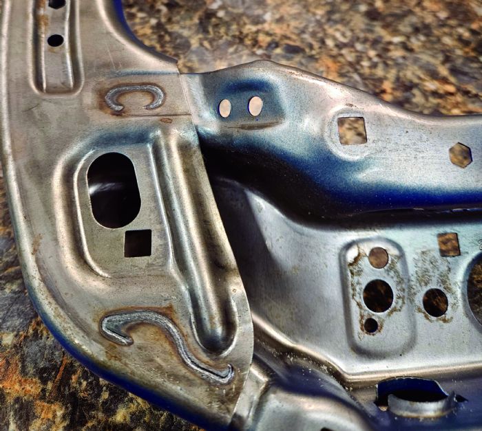 Well-versed in VISI and AutoForm for die development and simulation, the firm’s design team, when developing tooling for a new program, can compensate on the computer for a “first phase” of die development, Bufka explains. That initial phase has the team focused on avoiding splits and wrinkles. Here, he says, the “generic” material cards suffice.
“But what we’ve learned over time,” Bufka shares, “that helps to ensure precision forming of these AHSS grades is the need to obtain actual, physical material coupons from the customer. We then have the coupons tested at the service center so that we can tighten the n and r values and total elongation in the die-design software. That practice enables us to zero in on and compensate for twist and springback.”
Tight Tolerances to Enable Laser Welding
Such expertise allows O’Mara to then leverage the firm’s ability to develop tooling for challenging work such as seating components when bidding on new projects. “We cut our teeth on seating parts several years ago,” he shares, “and consistently meet tight tolerances in the range of 0.4 to 0.6 mm.”
Displaying some of the seat assemblies for which the firm has developed the tooling, Bufka explains that typically the seat sides include recliner brackets that are laser welded in place, as are the cross members. “These are dual-layer, sometimes triple-layer weldments,” he says, “where part flatness is absolutely critical—zero gaps allowed, so part fitup must be perfect, precise and consistent.”
Again, achieving such critical part dimensional tolerances requires precisely developed tooling, and Digital Tool & Die works to perform as much up-front die-engineering work as possible before cutting any tool steel, a practice that it’s consistently had in place for 2 yr. or so. “Simulation is our insurance,” Bufka says. “The days of figuring things out in the press are gone.”
 He offers a recent example of how the practice can pay off: “We recently completed a project for 1180-MPa DP steel,” he says, “where simulation proved critical to avoid surface cracking, and AutoForm has some new tools in place to look at that. Particularly critical is the trim edge, requiring careful attention to cut-edge condition—any nicks can lead to ripping during forming. AutoForm, along with using accurate material properties from coupon testing, led to a successful outcome.”
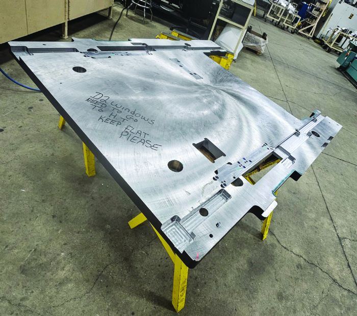
In another case, described by O’Mara, a seatback side member required a great deal of upfront engineering development prior to developing the tooling. “We took some arrows to get the project completed,” he says, “to enable the customer to obtain the required accuracy and precision. We typically strive to get new tooling to about 80-percent developed in engineering and on the screen, and then leave just that last 20 percent of die development to tryout on the floor.”
“You might only get 15 to 20 percent maximum allowable bilateral thinning,” Bufka adds, “and the material is not even 1 mm thick in some cases. And at the same time, we must control wrinkling and bunching. All kinds of upfront engineering goes into these parts, understanding what the material will do before we even build the tool.”
Tribal Knowledge
While upfront engineering development represents a core competency to ensure precision stamping at its customer, Digital Tool & Die has other tricks up its sleeve to help customers maintain critical tolerances as production runs hit their stride and tooling wears.
“We believe that the tribal knowledge inherent in our production team on the floor contributes to the success that our customers experience with our tooling,” O’Mara shares. “But there’s more to it than that. One key is the use of adjustable inserts in critical areas of the tooling, such as a restrike station. We want to provide our customers with the flexibility in the tooling that they need in order to adjust the die while it’s in the press, adapting for any changes in material properties or to account for tool wear. The goal: Allow the toolmaker to work on the die while it’s in the press and not have to go back into engineering and machine a new block.”
Another trick up its sleeve is a new module in VISI (from Hexagon), a morphing-faces option that, according to Hexagon officials, can be combined with all binder methods and mesh types, allowing the selection of faces to be retained as the original shape.
“Part-definition analysis has been improved (with VISI 2023.1) by adding etching recognition,” a Hexagon press release states. “A new algorithm automatically calculates the neutral fiber and obtains the most accurate unfolding calculation for part definition and step unfolding. The part flange unfolding function has been revised and enhanced to improve the quality of the results and remove some limitations. Part definition now enables users to extract the model’s ‘skin’ and use the flange-unfolding function by simply switching from face selection to edge selection and selecting the reference edge of the non-linear blend.”
Springback Compensation by Finite Analysis
Says Bufka: “Morphing is springback compensation by finite analysis. We have a laser scanner (a Hexagon Romer Absolute 3-m portable arm) that we use to gather part data to help evaluate, on the computer, springback and then compensate in the software. If we can’t move the material exactly how we want to via tooling modifications, we go back into engineering with the scan and manipulate the surfaces, knowing where we are dimensionally and where we need to go. We then take the die skins in CAD and make the needed alterations to manipulate the surfaces.
“We used to perform this exercise manually,” Bufka continues. “Using this new software module has allowed us to streamline the process from two or three days required to manually check a part and perform all of the calculations, to where we now take meta data from the laser scan and let the software do the work, all in just 2 or 3 hr. And, once we reengineer the die block, we save the file to the bill of materials for when the customer needs to replace it—accurate and efficient.”
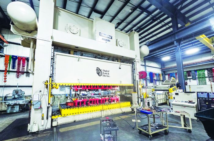
Finally, when it comes to tryout, O’Mara recognizes the firm’s impressive press-line lineup, with press size topping out at 1000 tons—two 1000-ton Blow presses, one with a 204-in. bed and the other with a 240-in. bed.
“The coil lines—a CHS and a couple of Perfecto lines (40,000-lb. coil capacity) in particular—feature technology that any production stamper would proudly own,” he says. “That equipment allows us to do much more than tryout, and we’re starting to perform a lot of customer launch support, and even some limited production stamping.” MF
View Glossary of Metalforming Terms
See also: Blow Press Limited, Hexagon Manufacturing Intelligence, Omax Corporation, Digital Tool & Die, Inc., AutoForm Engineering USA, Inc.
Technologies: Materials, Quality Control, Software

 Video
Video