Peter Ulintz Peter Ulintz
Technical Director

Expanding the Diemaker’s Toolbox

July 27, 2023
0
Comments


Tool and die makers are notorious for their toolboxes. Some toolmakers have so many tools that they require several toolboxes for storage. A typical toolbox might include a variety of hand tools and precision measuring instruments, along with an assortment of personally handcrafted specialty tools. The handcrafted tools tend to be a source of great personal pride. When I worked as a tool and die maker, my personally designed, handcrafted precision grinding vice was a most-valued possession.

At the time, I also was intrigued by the tools that filled other toolmakers’ toolboxes. Inevitably, I would ask, “What’s in your toolbox?” Sometimes I discovered a precision or handcrafted specialty tool that I didn’t know even existed. Other times I learned new ways to use the tools I already had.  

I suspect that much of my experience still holds true today, except that today’s toolmaker must possess a toolbox much different than what I worked with 40 yr. ago. The hand tools and measuring tools might be similar, but the specialty tools no longer are of the handcrafted variety. Common tools of the trade now include those used for surface-strain analysis, tensile testing, thickness-distribution plots and forming-limit curves. 

Historically, designing, engineering and building metal stamping dies represented a highly specialized undertaking, combining the elements of art, science and craftsmanship. Transforming a part drawing into a die that stamps tens of thousands—sometimes millions—of parts in a stamping press required considerable skill and experience. 

The Virtual Tools of Today

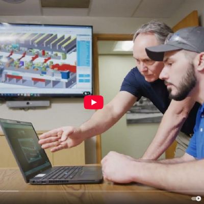
Modern die-engineering practices employ sophisticated computer-aided engineering (CAE) tools that help design and validate metal stamping dies. As a result, many tools have become part of the diemaker’s and die engineer’s virtual toolboxes, including those for interpreting stress-strain relationships; understanding material properties and the relationship of friction coefficients on formability; analyzing die structures under applied stress; and employing process optimization.

Not long ago, only highly skilled CAE analysts with master’s degrees or doctorates, working in automotive companies, steel research centers or major universities, performed process modeling. Today, user-friendly software enables process modeling by die-process engineers, tool and die makers, and part-estimating engineers. Nonetheless, a large gap remains between the skillset required to build, assemble and maintain dies, and the skills needed to troubleshoot stamping problems in the press shop. 

Troubleshooting Tools

A diemaker tasked to help troubleshoot problems in the press shop often searches for a solution within the die. Most diemakers can get a process running again, but perhaps at the expense of correcting root cause. The primary reason: Instead of considering the die as one input variable to a complex manufacturing system, diemakers view it as being the entire process. In general, diemakers lack vital process knowledge that many press technicians possess; thus, they are missing the “tools” required to find root cause.

To solve production-related problems, diemakers must understand the stamping process in terms of “math in motion.” What events are occurring at any given degree of press rotation? At what angle should the feed roll lift, close, start to rotate and stop rotating? What are the appropriate sensor window angles and what are their relationships to critical signal angles? Does press speed affect these event angles? 

For example, is feed inaccuracy or roll slippage responsible for distorted pilot holes in the strip? How is feed-roll slippage determined? What caused the slippage, roll pressure, feed acceleration or something else? Is signal lag time causing the pilot release to lift the roll late? Not understanding the correct answers might result in changing the programmed feed length. This is relatively easy to accomplish and it may correct the symptom (for now), but root cause has not been addressed. In extreme cases, especially when access to program changes is not available, the pilots in the die might be repositioned or removed entirely.

Another example: part flatness. With flatness identified as a critical part feature, the die often will include a restrike station. Here, a diemaker most likely will address the flatness issue in the restrike station, although straightener-roll depth settings or pinch-roll pressure may be the real source of the problem. 

When a diemaker’s only “tool” is die knowledge, production issues always look like die problems. What’s missing from your toolbox? MF

Industry-Related Terms: Die, Drawing, Grinding
View Glossary of Metalforming Terms


See also: Precision Metalforming Association

Technologies: Tooling

Comments

Must be logged in to post a comment.
There are no comments posted.

Subscribe to the Newsletter

Start receiving newsletters.