Pressure-Plate Strippers—Part 1
March 1, 2022Comments
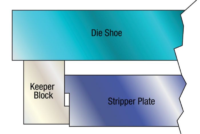
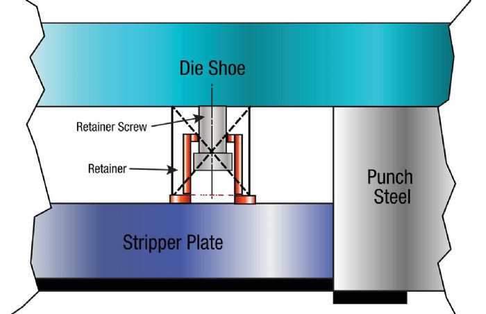
The term “stripper” applies to the stripping plate, keepers or retainers, and pressure system (springs, gas, rubber, etc.), which all aid in the stripping of stock material from around the punch steel.
 Most die design rules of thumb recommend that stripper pressure constitute approximately 10 to 30 percent of the cutting force. In general, softer materials and tighter die clearances require higher stripping force. But, every rule of thumb involves some degree of tradeoff for the convenience of applying the rule. In the case of stripping forces, the tradeoff is die wear.
Frictional forces inside of the die influence the amount of pressure required for stripping. In high school physics I learned that “Friction is FµN,” a convenient way to remember that friction (F) is the product of the coefficient of friction (µ) times the normal force (N).
The frictional forces associated with stripping force directly relate to the rate at which the cutting edges of the punch and die components wear. As a result, a primary design objective should be to reduce the value of the µ and N factors to produce more stamped parts between sharpening.
Factors that influence µ include: a) lubrication, which breaks down with process heat; b) punch surface finish, which contributes to adhesive wear; c) punch hardness, which often degrades over time due to poor sharpening practices; and d) the type of material being punched.
 Factors influencing N include: a) punch-to-die cutting clearance, which increases the normal force as the clearance is reduced; b) the ratio of hole size to stock thickness; c) the spacing between adjacent holes; and d) the cutting-edge conditions on the punch.
Stripper-Design Guidelines
Stripper construction plays a significant role in die reliability and durability. Consider these important design guidelines:
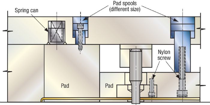
 Advantages of using spools: a) reduced space required on the die shoe as compared to keepers; and b) the round shape is readily machined, which reduces machining costs.
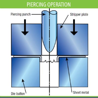

 Webinar