Key Size
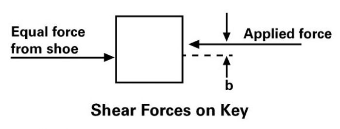
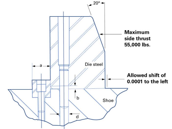
A major factor in key design (Eary & Reed) involves the size of chamfer on the back side of the die steel (dimension b in Fig. 1). This chamfer can vary greatly, from nonexistent to very large, especially if not specifically controlled on the die-detail drawing (e.g., note on drawing: “break all corners”). However, the size of this chamfer can prove important because it sets up the distance between the shear forces (Fig. 2).
Assume that chamfer b equals 0.060 in. What should the key width (dimension a) be if side movement is restricted to 0.0001 in., using a 6-in.-long key subjected to a 55,000-lb.f lateral load?
 Here we use deflection under shear forces (shear modulus) to solve for dimension a. For a steel key, in either the soft or hardened state, the shear modulus equals approximately 12,000,000 psi.
12,000,000 = (55,000/6a)(0.060/0.0001)
12,000,000 = (9,167a)(600)
a = [(9,167)(600)]/12,000,00
a = 0.45835 in.
In this instance, select a 0.500-in.-wide key.
Next, verify that the elastic limit of the key is not exceeded; otherwise, it will permanently deform (exceeding its yield strength in shear).
The amount of stress exerted on the key = 55,000/(6)(0.5) or 18,333 psi.
Shear-stress data prove difficult to acquire, with achievable repeatable results proving just as difficult. For this reason, many handbooks and other sources specify shear stress as a percentage of the material’s tensile strength. A common presumption: Shear strength for mild steel totals 60 to 70 percent of its tensile strength. That said, let’s assume the key shear strength to total 60 percent of its 80,000-psi tensile strength (1018 CRS), or 48,000 psi. That means that the stress (in shear) applied to the key lies well below its shear strength. The key design, in terms of material selection and cross-sectional width, would be appropriate for this application.
It also is possible to calculate dowel-size requirements to prevent shifting in the absence of a key. This is not a good die practice, however, as the size of the dowels would be very large. In the example provided above, two dowels in diameters of approximately 1.500 in. would be required.
As a rule, dowels position the die component and keys absorb lateral loads. In some instances, dowels and keys could be used in combination to control lateral forces, thus reducing the size of both. A better solution: Place the die section against a ledge or a pocket machined into the die shoe. The cross-section of the die shoe provides great rigidity.
Restricting Die-Component Bending
Lateral loads cause some die components to deflect or bend, such as a cantilevered beam, rather than shift sideways. This can be problematic when working only one side of the sheet metal, such as when notching, trimming and flanging using tall die steels.
One method for limiting this deflection: Control the height-to-width ratio of the die component. As a rule, try to design the width of the die component as larger than its height. This provides good stability and some resistance to tipping and bending. This is not always possible, especially with long, narrow cutting blades.
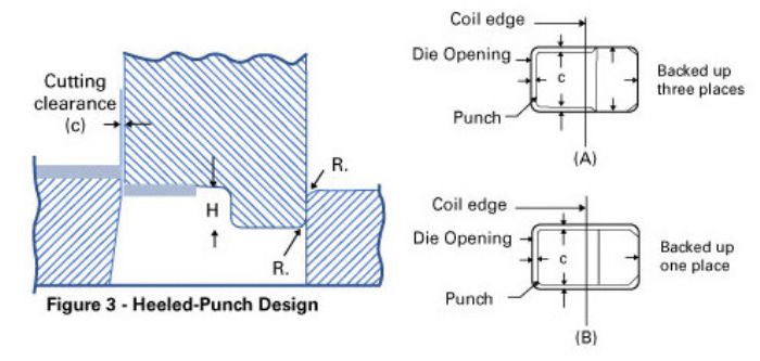 When the overall punch height must be greater than its width, consider a heeled-punch design. Fig. 3 depicts a heeled-punch design frequently found in notching stations. The cutting forces acting on the left side of the punch are unopposed by the opposite (right) side of the punch. The cutting forces will cause the punch to deflect away from the cutting action, unless a heel is added to the opposite side(s). The purpose of the heel: support the punch to restrict lateral (bending) movement. The same principle applies to heeled punches designed for trimming and flanging operations.
The heeled portion of the punch in Fig. 3A is designed as a slip-fit (approximately a 0.0002-in. clearance) on three sides inside of the die opening. This provides control in three directions. Because the cutting loads are equally opposed on two of the three cutting sides, the punch could, alternatively, be heeled (Fig. 3B).
The heel height, H, must be tall enough to provide an adequate bearing surface and support the punch before cutting or forming. Be sure to provide a lead radius on the heel edges and the corresponding die-opening edges. Do not make the radii too large, as this will reduce the heel-bearing area. MF
Industry-Related Terms: Bending,
Blanking,
Die,
Dimension,
Drawing,
Forming,
Notching,
Ram,
Surface,
Tensile Strength,
TorqueView Glossary of Metalforming Terms Technologies: Tooling


 The forces generated by forming and cutting operations act together with mounting screws to produce a normal force great enough to prevent shifting or tipping of the die components. Some dies are less susceptible to shifting and tipping than others. A simple blanking die or punching die for a circular cut, manufactured from a single piece of tool steel with cutting clearances equal around its perimeter, produces balanced side thrusts.