Improving Progressive Die Performance—Part 3
November 29, 2021Comments
In this final installment of a three-part series, we explore the effects that coil-feed height and pilot-release timing have on process efficiency and accuracy.
Feed Height
 Feed height, also known as pass line, refers to the distance above the bolster plate that the coil material exits the press-feed unit and enters the die. Progressive dies with little or no strip lifting have a feed height equal to the height of the lower die surface. Stampers should adjust feed height at each setup so that the strip material enters the die exactly parallel with the height of the lower die surface—especially important when running thin materials. Slight bending of the material due to differences in die height and feed height reduces the strip stiffness, making it susceptible to buckling.
One method to ensure parallelism: Measure the die surface height with an indicator, then set the feed bridge (material support) and feed unit to the exact same reading (Fig. 1).
Set feed height for dies using stock lifters or lifter rails differently. Here, feed height should measure exactly parallel to the height of the lifter rails to allow smooth feeding of the coil strip. Avoid feeding the material downward or upward into the die. These conditions may cause the material to bind or jam in the lifter rails.
Feed Roll (Gripper) Lift
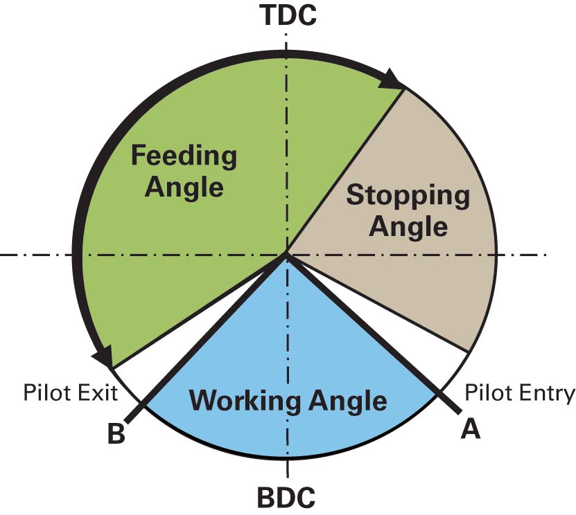
 After the coil stock has moved to its predetermined progression (pitch), the feed rolls should open after the tip of the pilot punch travels deep enough into the material to prevent the strip from slipping backward, but before the full diameter of the pilot punch has entered the material. This allows the coil strip to be positioned accurately using the pilot pins in the die (point A in Fig. 2). This commonly is referred to as pilot release open (ON). If the pilot release opens too early on the downstroke, the strip can pull backward. Should the feed rolls open too late, the pilot punch can break off, oblong the hole or wear out quickly.


 For feed units that rely on pneumatic cylinders to lift and close the feed rolls or grippers, consider the delay time from when the signal is sent to open the feed and the actual time that the feed takes to open. The time required to charge the solenoid coil, activate the switch, exhaust air from one side of the air cylinder and pressurize the opposite side to lift or close the feed roll may take about 35 to 45 msec.
 Referring to Fig. 4, should the feed roll (gripper) be programmed to lift at 125 deg. in a press running at 60 strokes/min., it will not actually lift until 137.6 deg. assuming 35-msec lag time, or 141.2 deg. assuming 45-msec lag time. The same delay will occur when signaling the feed to close. If press speed decreases or increases, the pilot-release timing also changes.

 Webinar