Improving Progressive Die Performance—Part 2
November 1, 2021Comments
Factors affecting performance of progressive dies include carrier design, strip lifting, strip guiding and strip feeding, as discussed last month. Another major factor: press maintenance. The press ram and bed must be flat and parallel to one another, and the ram must travel perpendicular to the bed with accurate guiding provided by the press gibbing system.
In addition, stampers must recognize the potential for punch and die misalignment due to ram tipping, and damage caused by misfeeds due to poor feeding and pilot release timing.
Minimize Ram Tipping
Maintain an even distribution of the force across the ram face to ensure good part quality, improve die life and reduce press maintenance. Greater cutting and forming forces in the die on one side of the press ram, relative to the press centerline, causes the ram to tip in the direction of the lower force (see figure: Press-Ram Centerline). Such movement occurring with the punches engaged with other die components can cause excessive wear or damage.
The ram in a single-connection press acts much like a teeter-totter, with the pitman connection serving as the fulcrum. A centered load prevents the ram from tipping left or right. Find moments of force that cause tipping by multiplying individual forces in the die by their distance from the press-ram centerline. Because these moments of force cause the press ram to tip, they’re also called tipping moments.
Using the press-ram centerline as the origin (zero), distances to the left are assigned negative values and distances to right, positive. Using the figure as an example, we can determine the following in Table 1.
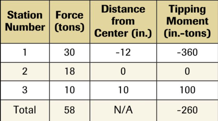 In a perfect world, the sum of all of the moments, the resultant moment, will equal zero. But, designing and building progressive dies with perfectly centered loads often is impractical.
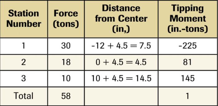
For a non-zero resultant moment, a negative value indicates the resultant moment positioned to the left of the press centerline. Positive values locate to the right.
To find the center of load, divide the resultant moment (-260 in.-tons) by the total press force (58 tons). The result: -4.48 in., meaning that the center of the load resides 4.48 in. to the left of the ram centerline. Centering the load requires the die setter to position the die centerline approximately 4.5 in. to the right in order to center the load directly under the connection. The result is shown in Table 2.
 The load, though balanced and centered mathematically, may not achieve this in practice. The calculations assume that all die forces occur simultaneously. However, forming and drawing forces are generated higher up in the press stroke than the cutting and punching operations, meaning that the die still can produce unacceptable off-center loads.
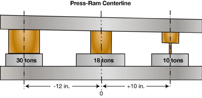 Setting the feed system properly, including the pilot-release function, often proves challenging for the die setter, yet is critical for successful progressive die stamping. While suppliers can provide highly accurate feed systems that practically eliminate the need for pilots in the die, many older feeds will overwork pilots beyond their original design intent due to improper setting of feeds. Avoiding inconsistencies in product quality and the likelihood of tool breakage or premature wear relies on proper feed adjustment or programming by die setters.

 Webinar