Mitering and contouring the corners will improve the ability of the blank to flow into both the corner wall and the adjacent straight sidewalls. Inserting offsets, darts or other features into the straight sidewall near the corner will impede any compressive stress relief from the corner into the sidewall.
Square boxes without flanges can be produced from circular blanks.
Effect of Die Bending Radius
Thinning in the vertical walls around the corner radius largely depends upon the bending radius of the die. Typically, the die-radius size should range between four times material thickness (4t) and 12 times (12t). Under the lower limit, fracture usually occurs, while wrinkling takes place at the bending area when the radius exceeds the upper limit. A small die radius will produce a higher degree of thinning in the vertical wall near the bending radius. This can be attributed to higher bending forces. Here, a larger die radius can help improve material flow.
Conversely, in the straight sides of the box, sheet metal flow can be extensive. A smaller die radius increases the bending loads, helping to restrict (reduce) material flow into the sidewalls. Thus, a die radius around the corner radius larger than the die radius along the sidewalls often proves beneficial.
Effect of Die Corner Radius
 We can use the size of the corner radius (Rc) to estimate the maximum draw depth for square boxes using tables and formability curves found in die design and metal forming handbooks. In the absence of other data, these rules of thumb apply:
- Part depths less than five times Rc: one draw operation
- Part depths from five to 11 times Rc: two draw operations
- Part depths from 11 to 16 times Rc: three draw operations
- Part depths from 16 to 21 times Rc: four draw operations.
Under ideal conditions, square boxes with small corner radii may be drawn to a depth of 80 percent of the box width. For production, assume a 70-percent maximum provided the presence of an optimized blank, ideal punch and die radii, die clearance that accounts for thickening in the corners, and use of appropriate lubricants.
 For the same blank size, the percentage of reduction at the box-corner radius increases with decreasing corner radius. A smaller radius results in a larger reduction ratio and a correspondingly higher drawing force. For a large corner radius―when keeping the overall dimension of the box consistent―the percentage of the bending and unbending zone decreases with respect to the entire perimeter of the box, while the drawing zones at the corners become more dominant. Because drawing operations require more force than simple bending, we should expect higher punch forces as the box shape approaches a circle (i.e., four large corner radii with little or no sidewall).
Effect of the Sidewalls
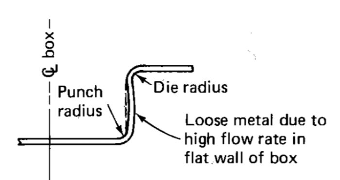
The longer the box sidewall the more freely the material can flow. The fast movement of material into the flat box wall often results in excess material. Rather than a tight sidewall, it instead slightly curves from punch radius to die radius (Fig. 2). This frees the box to oil-can, or snap back and forth when a load is applied. Possible solutions: Add draw beads, spot the blankholder (or die) face, sharpen the die-entry radius, or tailor lubrication at the corners (to reduce friction) and the sides (to prevent galling).
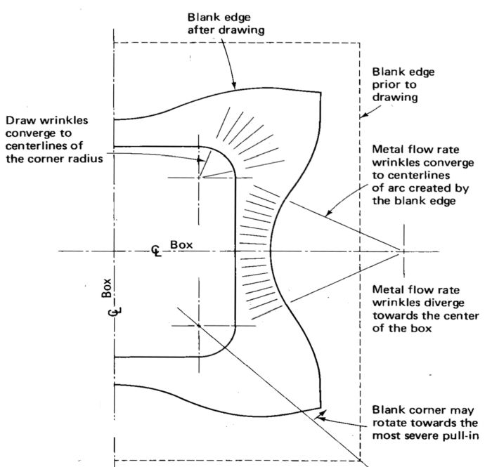
Sidewall wrinkles associated with flow rate, also called flow-rate wrinkles, diverge toward the die radius (Fig. 3). The cause of these wrinkles differs from that of the convergent draw wrinkles at the box corners.
Boxes with nonvertical (tapered) walls prove more susceptible to wall wrinkles. Restraining forces must be increased and allowable box height decreased. A box design with 20-deg. tapered walls may require a decrease in draw depth of 25 percent or more. MF
Industry-Related Terms: Bending,
Blank,
Circle,
Corner Radius,
Corner,
Die Clearance,
Die,
Dimension,
Draw,
Drawing,
Edge,
Forming,
Thickness,
WrinklingView Glossary of Metalforming Terms Technologies: Tooling


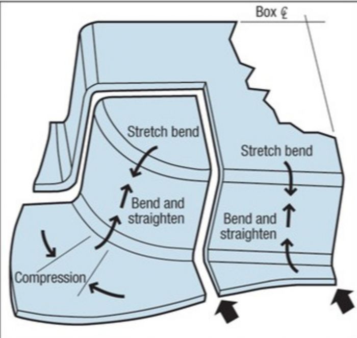 Unlike cup drawing, box draws contain two opposite modes of deformation. The behavior at the four corners resembles that of conventional cup drawing. This involves five stages: bending, straightening, friction, compression and tension. The corners will include compressive deformation on the material moving toward the die radius and tensile on the material drawn over the radius.

 Webinar