Conventional presses only provide unidirectional and constant-speed shaft rotation during production; stampers cannot fine-tune the slide speed for each forming operation. Conversely, servo presses allow for change in direction and speed. Hence, stampers can adjust a servo press to fine-tune the speed at impact or during forming while maintaining the highest possible production rate.
Another advantage of a servo press: The shaft does not need to complete a 360-deg. rotation. Rather, stampers can program a servo press to change the direction of rotation at predefined angles (pendulum mode) to increase the production rate. For example, limiting the rotation per stroke between 90 and 270 deg. (180-deg. rotation) can increase the production rate compared to a 360-deg. rotation. Simply put, position and speed control in a servo press can improve the forming process and increase production rate.
Synchronization
 Inputs and outputs (programmable limit switches, die protection, tonnage monitor windows, auxiliary outputs, blow offs, etc.) must be coordinated with the press motion. Doing so with a conventional press occurs rather simply, as the angular position of the shaft increases consecutively between 0 and 360 deg. As a result, each angular position of the shaft occurs a single time within the stroke. Conversely, with a servo press, due to the motion flexibility a given angular position of the shaft may repeat several times within a single stroke. This requires an additional step in the synchronization process.
To ensure proper function of all systems linked to a servo press, we use a real and a virtual angle. The real angle indicates the angular position of the shaft at a given moment, while the virtual angle is a constant-time-based representation of the complete motion profile. For example, a production rate of 60 strokes/min. will take 1 sec. to complete a full revolution, 0 to 360 deg., of the virtual angle, even though the real angle may accelerate, decelerate or change direction during the stroke. The press controller performs this conversion automatically.
The virtual angle indicates how far in time the motion profile is from completing a stroke. Consider the real angle oscillating between 90 and 270 deg. with the servo press operating in pendulum mode. In the forward stroke, the virtual angle will automatically be set in such way that 0 virtual deg. corresponds to the initial pendulum angle, 90 real deg., and 360 virtual deg. corresponds to the final pendulum angle, 270 real deg. (Fig. 2). If we add acceleration or deceleration to the motion profile, a virtual 180-deg. angle would not necessarily mean that the press is at BDC. Instead, it would indicate that the slide has moved half the time required to complete a stroke. The use of virtual angle opens an infinite number of possibilities for synchronization of ancillary equipment and other external actuators.
Torque Transmission
 Mechanical presses, conventional and servo, apply vertical force as a result of the available torque within the system, with a direct relationship between the magnitude of the vertical force and the torque. Due to the nature of their systems, conventional and servo presses show opposite torque characteristics at low and high shaft speeds.
In conventional presses, torque available depends on the size of the flywheel and clutch, which in turn deliver torque to the shaft, either directly or through gears. The flywheel must rotate at or above a minimum speed in order to provide enough torque to satisfy the rated tonnage of the press. The clutch serves not only as a torque transmitter but also as safety mechanism. The clutch will slip should the press experience a reaction torque higher than the capacity of its components, interrupting torque transmission (assuming correct setting of clutch operating pressure).
In a servo press, which lacks a flywheel to deliver torque or a clutch to limit it, the servo motor must deliver the required torque to the shaft, either through gears or directly. With a motor direct-drive configuration, the motion controller is able to protect the system against excessive reaction torque. The absence of a flywheel and clutch in a servo press reduces not only the number of components and their maintenance, but also helps to reduce system inertia. (For example, the low-inertia design of a Nidec Minster servo press design allows for fast changes in motion conditions for the given torque capacity, and allows for high performance.)
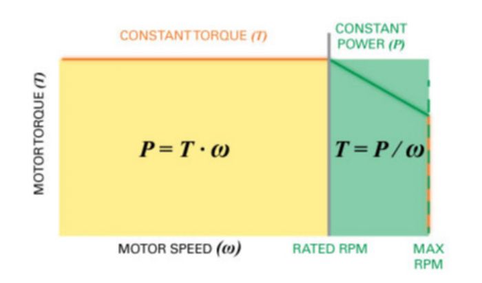
Due to electric principles beyond the scope of this article, the torque available in a servo motor peaks and remains constant up to a rated speed, but decreases at a constant power rate above such speed (Fig. 3). This behavior has positive and negative connotations. On one hand, servo presses would outperform conventional presses for applications requiring full capacity at low speeds—die setup, for example. And, conventional presses will perform best for applications requiring full torque at maximum speeds.
Tonnage Available
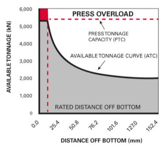
 As mentioned, the available tonnage is related to the torque available within the system. For constant torque, in a slider-crank press the available tonnage will increase with decreasing lever-arm length. In other words, for constant torque, available tonnage increases with decreasing distance off bottom (DoB), as described by the available tonnage curve (ATC, Fig. 4). Looking at the ATC, the minimum tonnage available occurs near the halfway point in the stroke, while the maximum tonnage available (or press tonnage capacity, PTC) occurs at the rated DoB. Theoretically, the available tonnage could reach infinity at TDC or BDC, where the lever arm is zero. However, that would compromise the press structure at tonnages beyond the PTC and it should be avoided.
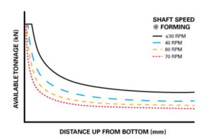
If the available torque changes, the ATC also will change, and so it’s important to understand the differences between the tonnages available in a conventional press compared to a servo press. For practical purposes, we can say that in a conventional press, the ATC does not change with shaft speed within the operational-speed range. Conversely, the ATC of a servo press is scaled down as we exceed the rated speed (Fig. 5). This results from the decreased available torque above rated speed in servo motors. Torque reduction in the servo motor also leads to a decreased rated DoB above the rated speed (Fig. 6). When looking at the ATC in a servo press, do not confuse shaft speed and production rate. Shaft speed refers to the actual rotational speed of the shaft, while the production rate refers to the number of parts being produced per unit of time.
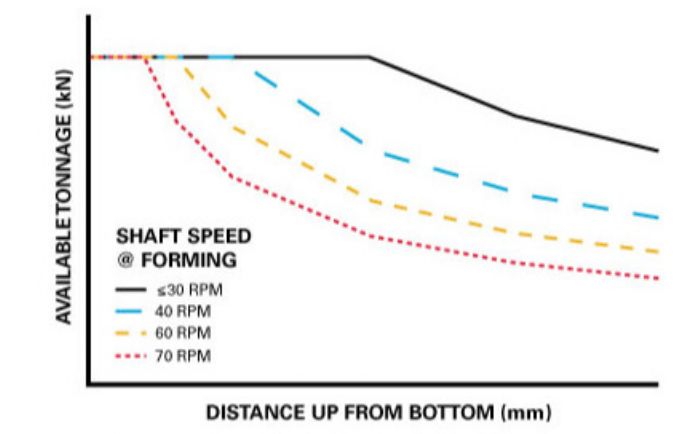 In many cases, this scaling-down-of-ATC phenomenon does not represent a significant disadvantage for servo presses, as many jobs do not require maximum motor torque. For those that do, we can decrease the shaft speed during forming in order to have full tonnage available. And, increasing the shaft speed during the nonforming portion of the stroke would help to maintain the production rate as high as possible. Nonetheless, take care to understand the ATC versus shaft-speed variation with servo presses.
Available Energy
The power supply of the press dictates the energy available per unit of time. Conventional and servo presses employ different systems to store energy, and due to these differences, conventional and servo presses show opposite trends regarding energy available at low and high production rates. Again, do not confuse production rate and shaft speed.
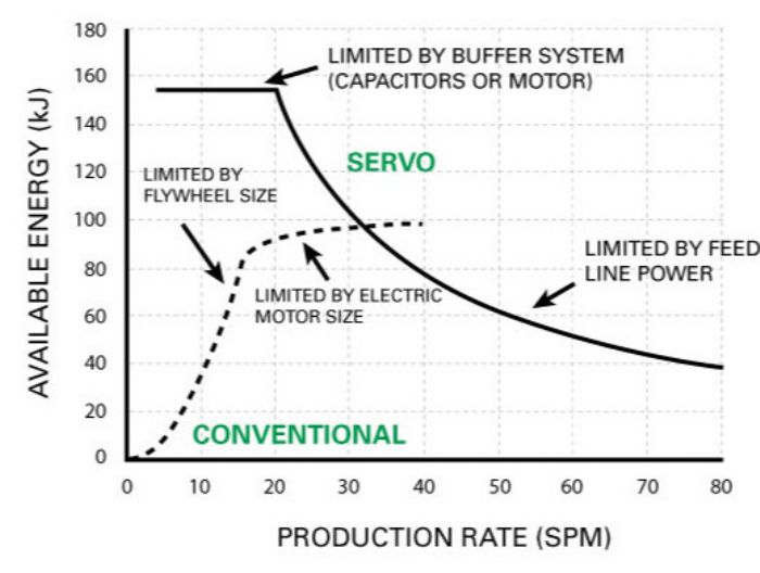
In a conventional press, the energy available depends on the size and speed of the flywheel, and the size of the main drive motor. As the flywheel rotates faster, the amount of stored energy increases. This energy is consumed during the forming process and replenished by the drive motor during the nonworking part of the stroke. The faster the speed, the less time the motor has to restore the energy, thus the system is limited by the power of the drive motor and its ability to restore the energy in time. The available energy curve (AEC, Fig. 7)) captures this behavior, relating the energy available to the production rate.
In a servo press, the energy flows directly from the electrical supply line to the storage devices, and then to the servo motor. The capacity of these storage devices determines the maximum amount of energy available during forming. Starting at low production rates, the full amount of energy is available as there is enough time to replenish the storage system to its full capacity, an advantage over conventional presses. Once the replenish time becomes insufficient, the energy available starts to decrease above a threshold determined by the size of the electrical supply line and capacity of the energy storage. Due to the storage capacity of modern devices, servo presses typically have larger amounts of energy available. This makes servo presses more desirable than conventional presses when dealing with high-energy consumption applications.
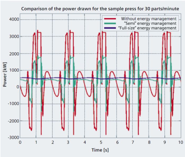
 Different energy-management systems exist for servo presses, depending on how the system delivers energy. Delivering the required energy directly through the servo motor does not require energy management. A semi energy-management system delivers energy by the motor and the storage system. And, a full-sized energy-management system provides all of the energy required in the storage system.
Applications implementing some level of energy management will experience a more uniform power demand from the grid, resulting in lower peaks (Fig. 8). Moreover, an energy-management system will reduce the power pulled from grid and the size of the transformer required, while increasing the efficiency factor of the energy used. On the other hand, these setups will increase the number of electrical components in the servo press, which can complicate maintenance procedures. In general, however, the benefits of an energy-management system overcome any maintenance concerns.
When to go Conventional, and When to Choose Servo
In general, servo presses can outperform conventional presses when applications require:
- Full energy and tonnage at relatively low speed
- Low forming speeds while maintaining high production rates
- Reduction of vibration, reverse tonnage or impact load
- A wide range of stroke lengths (one servo press can emulate the motion of various configurations of conventional presses)
- Special motion profiles
- Improved synchronization with transfer and feed systems.
 In other cases, a conventional press can be a better option for:
- Shops looking to make a lower initial investment
- High-speed applications
- Production of similar and relatively simple parts
- Applications with low energy requirements (e.g., blanking or piercing)
- Applications requiring maximum shaft speed and full tonnage. MF
See also: Nidec Press & Automation
Technologies: Stamping Presses


 Understanding the differences between a conventional (flywheel) mechanical press and a servomechanical press is key in selecting the right press for a given metal stamping application. While servo presses bring flexibility, stampers still prefer conventional presses for certain applications. While stampers can find plenty of literature describing the characteristics of conventional and servo presses, discussion of the fundamental differences between these two types of presses is limited.
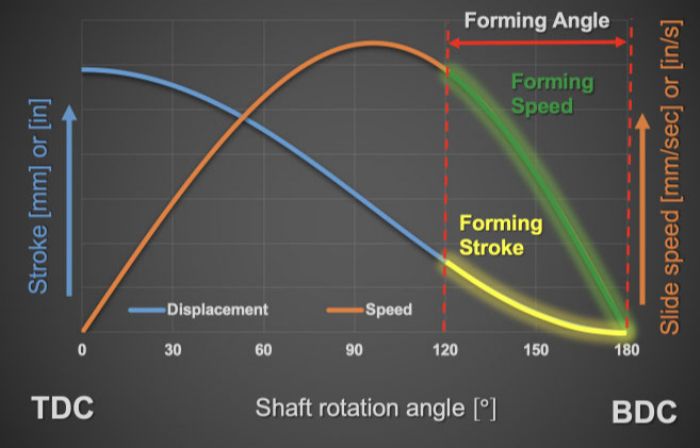
 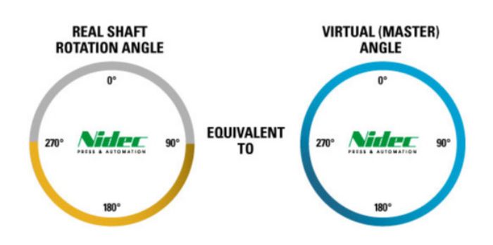 …are some of the most noticeable differences between conventional and servo presses due to their drive system, flywheel and servo motor, respectively. Nevertheless, the principles of motion are the same, and stampers should completely understand them. For both types of presses, rotational motion of the shaft(s) translates into vertical slide motion. The most common mechanism for this: the slider-crank (Fig. 1), which creates a nonlinear relationship between shaft rotation and slide displacement. Slide speed tends to zero as it reaches top dead center (TDC) and bottom dead center (BDC), where slide travel changes direction. Keep in mind that the slide travels the fastest near the midway point of the stroke, and that slide travel speed at the moment of contact with the blank and tools can influence the forming process, press life and tool life. For example, we can expect higher vibration and noise resulting from higher impact speeds. Other factors affected by slide speed during the forming process include temperature, lubrication, material formability, reverse load and snapthrough.