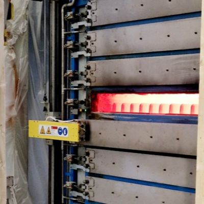

 HSBS arrives at the end user as an unfinished product, with a tensile strength of approximately 550 to 600 MPa. The forming process—5 to 10 min. in an oven at 900 to 950 C, forming in a press, and then rapid cooling—transforms the steel into a finished product with a tensile strength of 1500 MPa.
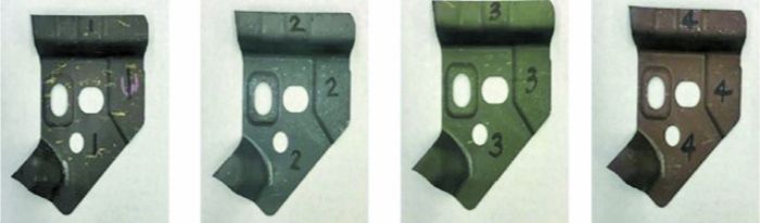
 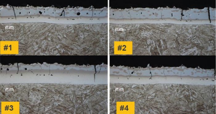 We easily can spot these differences in HSBS resistance as the materials have a slight change in appearance (Fig. 1, parts pulled from the same bin are of four distinctly different colors). This creates a moving target with regard to resistance each time that we try to weld a fastener to these parts, a target difficult to hit when using conventional mid-frequency direct-current (MFDC) weld controls because they supply constant current and generate inconsistent heat at the weld interface. The result: Fasteners may fail pushout requirements and potentially fall off. Also noteworthy: Even though the coating is very inconsistent, the base metal holds its desired integrity.
Hardness Caries from Steel to Fastener
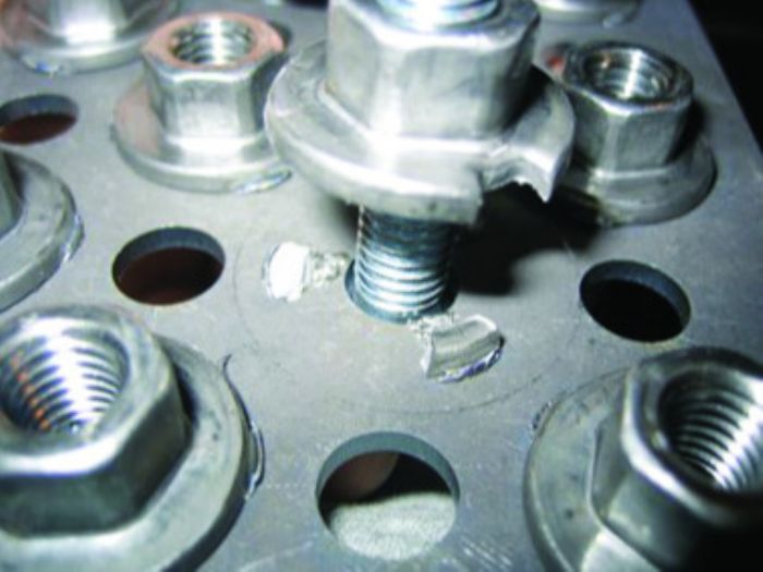
 Metal formers also typically overlook and fail to account for the difference in the hardness of the HSBS and the fastener itself. According to the best data we can obtain from fastener manufacturers, fastener tensile strength ranges from 400 to 450 MPa, a stark contrast from the 1500-MPa tensile strength of formed HSBS. This means that traditional destructive testing can be difficult to gauge; we have seen fasteners fail before the base metal, which can result in anomalies in the final pushout-test data.
Why MFDC Welding Doesn’t Fit
Although MFDC can maintain a programmed current output within ±2 percent, traditional MFDC weld controls have had limited success when welding fasteners to HSBS, which we attribute to the inconsistency of the post-processed AlSi coating. When the weld current is held at a steady state and the resistance rises above the baseline, increased energy is created at the fastener interface. This results in excessive heating and reduced weld strength. The same problem can occur inversely when resistance drops below baseline and results in an insufficient amount of heat generated at the projection interface, causing a weak weld.
 So, as good as MFDC performs when welding HSBS material in a normal flat-to-flat configuration, MFDC is not recommended for fastener welding to HSBS.
Alternatives to MFDC
Knowing that traditional MFDC weld controls cannot overcome the challenges created by inconsistent AlSi-coating thickness, we have a few choices:
- Perform 100-percent inspection of each fastener and reweld any that fail.
- Tack weld (using gas-metal-arc welding) each nut to act as a safety weld.
- Use a capacitor-discharge (CD) fastener welding machine, which will overcome the resistance inconsistencies and deliver a repeatable process.
 CD welding uses the energy stored in a bank of capacitors to deliver energy to the weld. A capacitor bank of a specific capacity (C) is charged to a high voltage (V), where the energy available to the weld secondary, E:
E=1/2CV².
 Because C is fixed, the voltage is adjusted to change the energy available to the weld. For each weld to form using the same energy level, the capacitors are charged to the same voltage. That fixed amount of energy stored in the capacitors then is applied to the primary side of the weld transformer, and the transformer steps down the voltage to a level appropriate for welding.
Note, however, that the current delivered to the weld on the secondary side of the transformer is not fixed or controlled. Ohm’s law tells us that V=IR; the current on the secondary side equals voltage applied divided by the resistance of the secondary (I = V/R). As resistance increases, current decreases. The inverse also is true—as resistance decreases, current increases.
This makes the CD weld control the perfect tool for welding fasteners to HSBS base material. Fig. 5 shows the current output from a CD welder with an 8-mm fastener at 680 V programmed, and Fig. 6 shows the current output from a CD welder welding through a ½-in.-thick copper bar—without a fastener—also at 680 V programmed. While this is a somewhat dramatic representation on how the CD weld control works, we only collect this data to benchmark each welding machine before it leaves the shop floor.
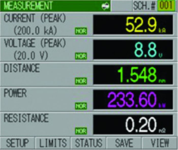
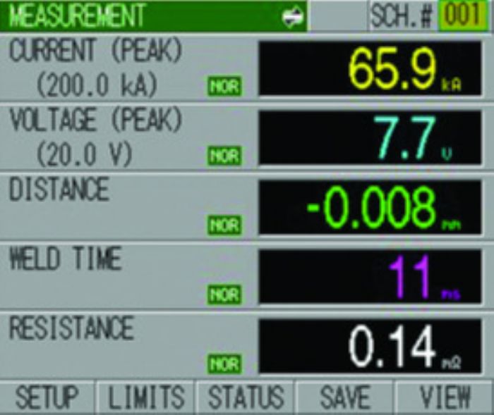
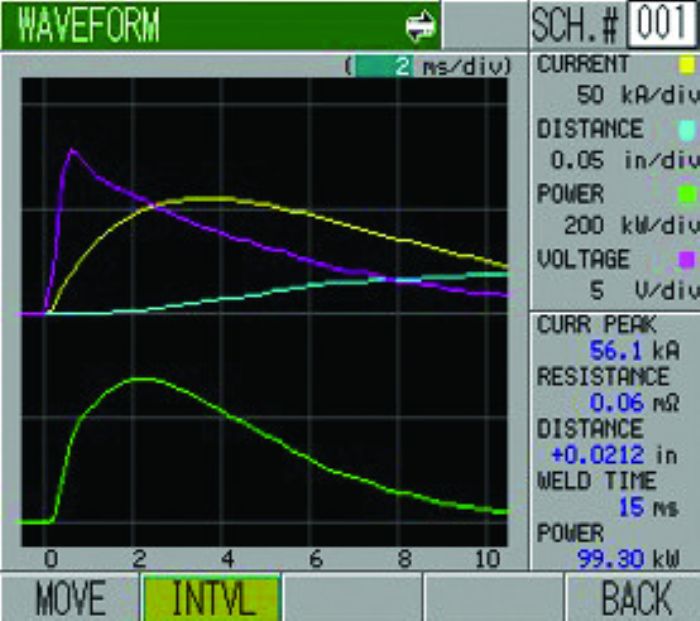
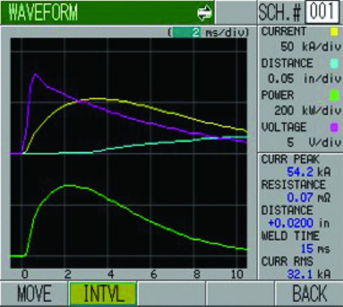
Finally, Fig. 7 shows real data from a single machine using an actual application. Notice the difference between the current and resistance readings—each weld has a different resistance signature and, therefore, a different current output.
Harnessing and Controlling the CD Energy
The last piece of the puzzle—and the most overlooked: the ability of the weld mechanism to harness and control all of the energy supplied by a CD weld control. A properly designed projection welder makes the process easy and trouble-free.
Let’s start with the welding-machine frame, which must be rigid with little to no deflection (about 0.002-in. deflection at a weld force of 7500 lb.) Because the average weld force for a HSBS fastener weld is approximately 3000 lb., standard fastener-welding machines typically will not suffice. And with estimated acceleration rates between 25 to 30 Gs, the last thing we need is a side-loaded force slowing the forward movement of the ram.
In addition, a standard projection-welding machine has a weld time of around 160 msec, enough time to maintain consistent force across the weld interface. However, a CD welder has a much more difficult task as weld time is less than 10 msec and requires much greater force.
Lastly, because heat generation in a CD resistance weld directly relates to contact resistance and not bulk resistance, the rate of acceleration of the projection collapse is much greater than in a traditional weld. This requires appropriate mechanical response, accomplished by properly sizing the welding-machine cylinders, ram and the fast follow-up mechanism for each application. Digging out an old welding machine with a die-cast ram and using roller cams with grease fittings and coil springs for follow-up is not an option for CD welding. MF
The authors credit Kevin Gunning, director of QSS, Amada Weld Tech, for contributing to this article.
View Glossary of Metalforming Terms
See also: Weld Systems Integrators, Inc.
Technologies: Materials, Stamping Presses, Welding and Joining