Freedom from Constraints
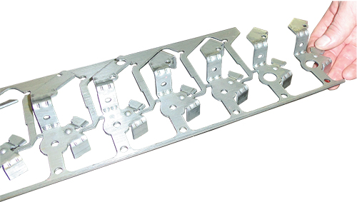
While each job varies, Bobby typically begins a job in VISI by importing a solid model of the final part to be produced. It’s his job, with help from VISI, to deconstruct the part and create a working model of the strip that will in turn create the final product.
“I have never had any problems importing into VISI,” he says “Nothing gets deformed or has multiple surfaces—there’s no loss of integrity. If it’s not a complete solid- —if there’s missing information—the software corrects the bad geometry.”
Because the software is equipped with an extensive range of translators, designers can work with data from virtually any CAD source. It rejects corrupted geometry during the process of importing CAD data, which means that Bobby can begin each job with the best possible information.
“With other software I’ve looked at,” he says, “it doesn’t appear as though you have as much freedom. There are no constraints on any solids in VISI—every solid can be manipulated so I can alter the imported geometry.”
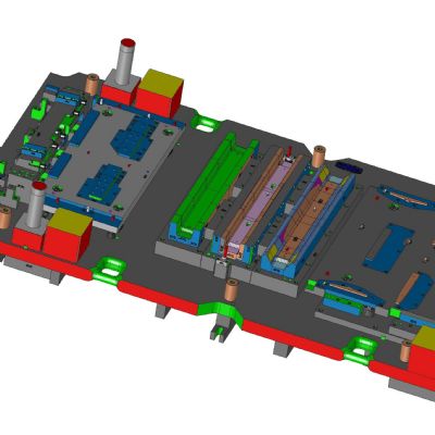
With the data imported, he determines where the entry point will be made on the die. “Once I get all of the stations unfolded,” he explains, “I can bring it into the software’s strip study and build the components around the strip.”
VISI then formulates the part-unfolding process, allowing Bobby to plan each forming stage, by dynamically adjusting bend angles. The solution also allows him to incorporate parametric features—ribs and bosses for example—that can be used or deactivated throughout the forming process. With flexible editing, stations can easily be added or removed.
VISI enables Bobby to easily generate 3D strip layouts, on which he can use the software’s automatic blank alignment, rotation and optimization functions to create the most efficient strip possible. The software also includes an automatic 2D-strip-plan option, which assists in punch design and includes fold lines.
“I start with the last station and work backward, deconstructing the part and breaking it down,” Bobby says. “The strip basically is the plan of how we’re going to make the tool from a block of steel.”
Generating the 3D Strip Layout
VISI enables Bobby to easily generate 3D strip layouts, on which he can use the software’s automatic blank alignment, rotation and optimization functions to create the most efficient strip possible. The software also includes an automatic 2D-strip-plan option, which assists in punch design and includes fold lines.
“A lot of the functions are created directly for the die world,” he says. “And many are automated, so I rarely need to use a calculator.”
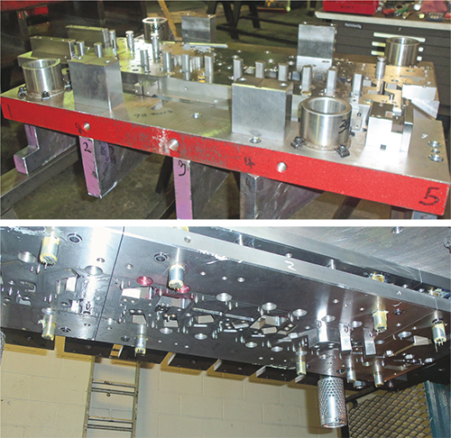
Other features enjoyed by Bobby include the automatic and semiautomatic functions supporting the creation of shearing punches. Once those punches are created, he can move them quickly and efficiently to different locations on the strip with simple drag-and-drop placement, at the click of the mouse. The flexibility of the process has made designing what once were considered challenging progressive dies a simpler process.
“If one option doesn’t work, there’s always another option,” Bobby says. “It isn’t the software that makes me ask, ‘Does it do this?’ It’s more, ‘How do I want to do this?’ The interface is completely customizable, and most functions have multiple options for getting me where I need to go.”
He also credits the collision-detection capabilities of the software for helping him create error-free press-ready designs. While DeCore tests its dies inhouse, all production of final parts takes place after the finished product has been delivered to the customer.
“Being able to see the 3D model and check interferences helps save time in the press,” Bobby says.
The 3D-2D Shuffle
Bobby also explains the value of being able to easily switch from 3D to 2D programming, without sacrificing data integrity. “This is important,” he says, “because I can’t print a 3D solid to show to customers, but I can print the 2D model.” MF
Article provided by Vero Software; 205/556-9199; www.verosoftware.com.
View Glossary of Metalforming Terms
See also: Vero Software
 Webinar