Die Build Simplified
December 1, 2016 Through innovative use of die-face-design software, Autodie can quickly and economically engineer and construct auto-panel tools.
 |
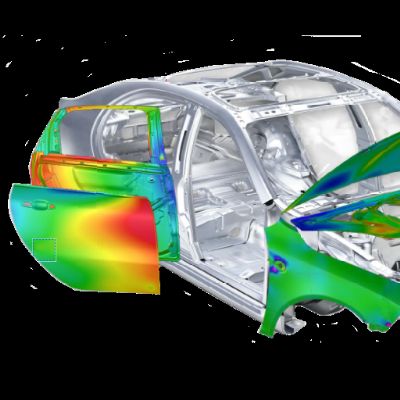
| Autodie, Grand Rapids, MI, designs and builds tools used to stamp Class A auto panels, among other parts. CAD-based software has paid dividends across the business, from quoting to validation to tool-path generation. |
Headquartered in Grand Rapids, MI, with a support facility in Salem, OH Autodie is a juggernaut in the realm of die engineering, program management, build and tryout. It’s 500,000-sq.-ft. plant in Grand Rapids features 24 CNC machines with a maximum table size of 43 ft., and 32 stamping presses with capacities to 4000 tons. Autodie, with 300 employees across two shifts, services the spectrum of automotive OEMs, specializing in stamping dies mainly for Class A body panels, door openings, fenders, hoods and lift gates. Agricultural and aerospace customers also benefit from the company’s expertise. More than 30 full-time engineering and design professionals supply tool and die builders with a 3D solid die design at Autodie.
Software Excels in Quoting and Beyond
With its behemoth operation, the company reasons that it can best control manufacturing costs through accurate and effective engineering. It must design, build and repair dies tasked with shaping mild and advanced high-strength steels as well as, increasingly, aluminum. Catia v5 software powers Autodie’s engineering efforts in designing dies made from primarily common tool materials. At one time, Autodie used software from AutoForm Engineering, Troy, MI, mainly in the quoting process to perform one-step forming analysis and determine blanks, according to Jon Brouwer, Autodie CAE team leader. More recently, the company has implemented the use of AutoForm-ProcessDesignerfor Catia, which seamlessly integrates into the Catia work environment, and is designed to rapidly create CAD-quality surfaces.
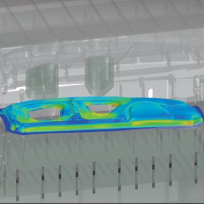
“We are currently using AutoForm’s incremental standalone product to simulate the forming process of a part from start to finish, including springback and overbend compensation,” says Brouwer.
Autodie began using AutoForm-ProcessDesigner late in 2015 and has expanded its use this past year into unique areas. One task for the software: In a quality loop, if, for example, an out-of-tolerance condition on a panel necessitates a change that must be retied to the die addendum surface. Catia alone can handle the task, but ProcessDesigner eases the process.
“ProcessDesigner is made for the sheetmetal and tool-and-die world,” explains Brouwer. “While tolerances are tight for radii and other die features, having to work within a software environment with tolerances well beyond what is required slows and complicates the process.”
Explains Michael Wright, Autodie assistant leader of programming: “We deal with parts having plus or minus 0.030-in. tolerances. ProcessDesigner provides the liberties to retie in that tolerance range in a timely manner. We see a 30-40-percent time reduction in tie-back when using ProcessDesigner within Catia.”
This forgiveness of tolerances and the ability to work with less-than-stellar data is a major selling point with Autodie’s engineers.
“We deal with customer data received from a wide variety of sources and CAD systems, and after all of the conversions we may encounter a poor quality surface here or there,” says Wright. “ProcessDesigner does a very good job producing good surfaces with lackluster data.”
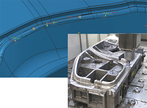
Creating fillet radii is another area where the software shines. In one case, an Autodie engineer had to redraw a wall nearly two-thirds of the way around an automotive door ring, which had been imported from a compensated and optical-scanned surface. In straight CAD software, this can be an all-day job as it can be performed only in small sections at a time, with considerable manual effort. With ProcessDesigner, the addenda draw wall was redrawn and a variable fillet radius created, from the bottom of the ring to the top, in only 15 min.


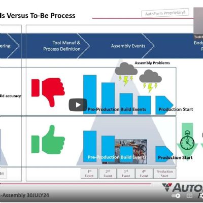
 Webinar