Optimizing Transfer-System Motion—The Money is in SPM
January 1, 2017 Simulation of transfer-press motion only to verify interference-free processing isnt good enough. Stampers should aim to optimize motion curves, following the advice offered here, to eke out additional strokes/min. (SPM) from their transfer presses.
There’s huge money in SPM (strokes/min.) rates, freeing up press time so that management can add tools to the lineup without adding presses. That’s the bottom line when it comes to optimizing transfer-press motion, according to Mark Hansen, simulation supervisor for T-Sim Solutions. Optimize the transfer cycle—up front and before the die and tranfer fingers are installed on the shop floor, says Hansen—and press availability will increase, as will the confidence of employees charged with getting new systems up and running with minimal tweaking.
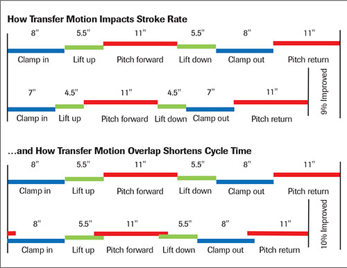 |
| Fig. 1—Lift-up to pitch, and then pitch to lift-down are two areas where motion can be overlapped quite a bit and alleviate a considerable bottleneck to add SPM (top image). Combining this with minimizing the distance traveled for pitch, lift and clamp (bottom), stampers can significantly improve cycle time. |
Translating SPM into profitability, says Hansen, consider an application where press speed, through transfer simulation and optimization, increases from 10 to 18 SPM. For an annual production run of 218,000 parts, press time drops from 420 hr. down to 246 hr. If press time costs a stamper $600/hr., that’s a 5-yr. combined savings of $522,000, plus the added 174 hr. of press time gained to run additional dies.
“It starts with addressing the information disconnect,” says Hansen, “between the die and transfer-system design and setup.” He laid out his system-optimization game plan at Metal-Forming magazine’s recent Servo Technology Experience and Conference held last October in Nashville (download the complete Conference presentation, available in full at www.metalformingmagazine.com/servo/schedule).
“Too many transfer tools are set up without having access to the CAD files or drawings, which would enable operators to properly set up the transfer bars and fingers,” he says. “Lacking sufficient setup instructions with the tools, a lot of time is wasted on the shop floor trying to tweak the setups merely to get the tools to run without interference.”
Hansen argues that first and foremost, stampers should require that tools arrive with detailed setup instructions that show exactly what the buildup should look like—where the bars and fingers go. Too often, he says, the press operator guesses at finger placement in the die; the trial-and-error method used to develop transfer timing just doesn’t cut it.
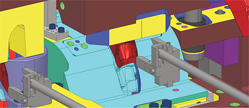 |
| Fig. 2—When it comes to looking for and removing obstacles to motion, look for components in the die affecting clamp-in and -out timing and travel distance required. Here, beveling the upper tool allows earlier clamp-in motion—this minor adjustment to the tool design can allow the transfer fingers to move into the die space several press degrees earlier in the press cycle. |
“When we run transfer-tool simulations, often we’ll look at several iterations of bar and finger placement until we find the best solution. Then we provide that detail to the stamper. This is just the beginning,” he says. “In addition, with our software we can calculate the optimum timing, based on preset limits for acceleration and velocity, to add SPM. This means determining where to start and stop motion, and—most importantly—where we can overlap motion. Even a two or three additional strokes per minute can allow a stamper to free up enough press time to add one or two jobs to a press’s production lineup.”
Bottleneck Hunting
Where can bottlenecks be cleared and SPM optimized? It’s all in the precise timing of the complex motion curves—clamp in, lift up, pitch forward, lift down, clamp out and pitch return. “Some of these bottlenecks kill production,” says Hansen. “These include travel distances and the time required to lift and clamp; pitch seems to typically be well understood. So when we look at time bottlenecks, we focus on when can we clamp in, and how long do we have to wait for the upper tool to be out of the way to start the clamp-in motion. Then, we look at what in the upper tool is coming down, determining when we have to clamp-out.
“Lift-up and pitch, and then lift-down are areas where we can overlap motion quite a bit in many cases, and alleviate a considerable bottleneck to add SPM,” he continues (see Fig. 1). “Stampers should pay close attention to opportunities to, for example, begin to pitch forward while still lifting up—look at the design of the tool for obstacles prohibiting an earlier start to the pitch motion. What’s preventing you from pitching forward, and what’s in the way that’s preventing the start of lift-down? The more you can overlap pitch and lift (up and down), the more free time you gain.”
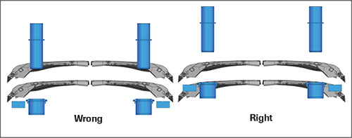 |
| Fig. 3—Another potential bottleneck to transfer movement relates to lower and upper die components such as pins and bushings. Position these just below the transfer height of the panel when the die is open. |
While this might seem logical, too many stampers, Hansen says, set some type of standard for delaying pitch following lift up regardless of the tool and process design. In many cases, he says, that standard might allow 1 in. of overlap between lift up and pitch forward, which may result in a paltry 0.25 improvement in SPM. He likes to say that by doing two things at once, the time needed for one is free.
“If that overlap can be extended to 3 in. (pitch forward 3 in. when lift-up ends),” he says, “you can gain as much as 2 strokes/min.—a significant improvement. Also, in most cases the greater the overlap the smoother the motion, which offers additional benefits—less thrust and acceleration, which improves panel control.”
Don’t Interfere with Die Design—Just Tweak
Motion optimization will impact die design to ensure that obstacles that can inhibit transfer motion are removed from the design. Therefore, it’s important that the optimization-simulation process occur before the die is completely designed, but not too early in the die-design process.
“We typically recommend going through the simulation and transfer-motion optimization process when the die is about 95-percent designed,” Hansen says. “This will ensure that the die is, first and foremost, designed for functionality and durability, and that the stamping process is repeatable and robust. With motion optimization, we’re not trying to force a redesign of the tool; we’re seeking modest improvements—perhaps with some added time and cost—to squeeze out SPM that will pay for itself very quickly, often in just a few days of production.”
Hansen’s presentation at the Servo Technology Experience offers several examples of the modest improvements to die designs that can add precious SPM to your transfer tools. “In most cases, when the software identifies obstacles that limit transfer time or restrict overlapping the motions,” says Hansen, “we can improve the die design.”
When it comes to looking for and removing obstacles to motion, look for components in the die affecting clamp-in and -out distance and timing. These include hanging upper components that delay clamp-in motion, components affecting when clamp-out motion must happen, and excessively tall die components that hamper overlap and require extra lift.
One example of such an improvement is to clear or bevel the upper tool (Fig. 2) to improve clamp-in motion timing—this minor adjustment to the tool design can allow the transfer fingers to move into the die space several press degrees earlier. Another example: designing the die to allow for the transfer fingers to retract later in the press cycle, by minimizing the height of hanging upper components and raising the height of lower components. The fingers have more time to retract without having to slow the press.
“The sooner you can clamp-in, and the longer they can stay in the die space,” Hansen stresses, “the higher the SPM can be; there’s more time available to move the panels. The goal is to quicken the process to the point where you’re still maintaining control of the panels; you don’t want to have to wait for something to get out of the way before clamp-in or clamp-out.”


 Video
Video