Stuart Keeler Stuart Keeler
President/owner

Track and Eliminate Rogue Forces

March 1, 2014
0
Comments


Stampings are becoming more complex. In one die, stampers can make parts that once comprised three separate stampings. Also, weight-reduction programs demand thinner-gauge parts with higher strengths, and dimensional specifications have tightened. All the while, lead time from order to delivery has been slashed. When necessary, troubleshooting must be quick, accurate and incorporate new concepts.

A friend who owns a medical clinic stopped me in his waiting room one day to describe a frustrating problem. The ceiling of the waiting room leaked water every time it rained. Removing several ceiling tiles, he found water dripping from a steel I-beam and applied several gallons of sealant on top of the roof at that location, with no success.

My immediate advice: “If your roof leaks, think like water not like a roof. The roof only becomes a problem when an outside force (the water) interferes with status quo. Track the water and you’ll find the solution.”

Examining the beam revealed water all along its length, due to its downward slope from the far end of the waiting room to the location of the leak. Removing tiles from the opposite end of the beam revealed a crack in the roof structure—the source of the problem.

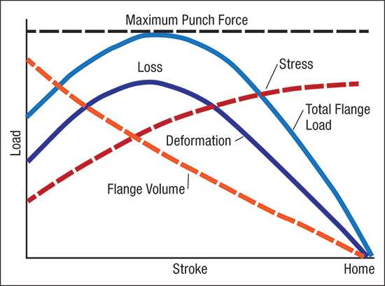
This concept applies to press-shop troubleshooting. If a stamping fails, think like force not like a stamping. Like the roof, the stamping only becomes a problem when outside forces interfere and alter the forming process. The amount of force divided by the crosssectional contact area becomes a stress that causes deformation (strain). Control and apply the force properly and the stamping will form according to print. Troubleshooters must track down and correct any unexpected rogue forces.

contact points where blankholder hits nitogren cylinders
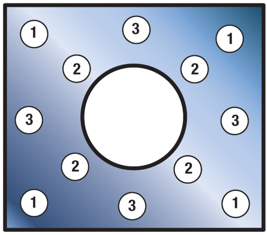
Fig. 1—Here’s one option for locating the first three of the six contact points where the blankholder hits the nitrogen cylinders, set at decreasing heights. The staggered contacts minimize severe initial loading and possible blankholder bounceback.
Three case studies will help illustrate this troubleshooting approach. The first: a symmetrical elliptical stamping with sidewall tearing als located toward the operator. Checking the stamping die dimensionally confirmed that both halves exhibited symmetry, and inspecting the blank failed to reveal any thickness variations. And, when forming test blanks oriented normally and reversed 180 deg., all tears still occurred toward the operator.

After reinstalling the die with a 180-deg. rotation, again the sidewall toward the operator tore. These tests strongly suggested that the problem was associated with the press. Circle grids imprinted on the blank indicated high levels of strain in the formed part, with slightly higher strain on the side of the stamping toward the operator. So, suspicion turned toward the blank holddown force, and eventually found the guilty party: longer cushion pins located on the operator side. These developed just enough additional holddown force to tear the stamping.

Our next case study involves a stamping made with a blankholder and pullover die. The blankholder clamps the blank well above bottom-dead center. The final stamping had areas of buckles, loose sheetmetal and other symptoms signaling intermittent loss of blankholder control. To gather data, the shop set up an ultra-high-speed video camera at the press. Reviewing the tapes showed the blank moving rapidly inward with a series of jerky movements. Also caught on tape: the upper blankholder hitting the blank so hard that it bounced upward off the blank and rebounded several times, thus allowing the unusual blank motion. The height of the bounces decreased as the blank formed over the die.

To generate the initial blankholding force, the press featured 24 nitrogen cylinders all set to the same height. To alleviate the unwanted blank motion, the shop set four equal-height cylinders to contact the blankholder at the same time (no. 1 in Fig. 1). Four more cylinders were set to a slightly lower height, followed by four more groups of cylinders set at even lower heights.

These load-stroke curves show what happens to the sheetmetal being formed into a deep-drawn cup.
Fig. 2—These load-stroke curves show what happens to the sheetmetal being formed into a deep-drawn cup.
The new setup applies force to the blankholder in smaller but increasing increments. All 24 cylinders contact the blankholder before the blank reaches the punch, so no total restraining force is sacrificed and the blankholder no longer bounces off of the blank. The video camera provided all of the data needed to solve the problem.

Lastly, consider the force diagram shown in Fig. 2, used to diagnose wall breakage during deep drawing of cups. The product of forming stress times flange volume represents the load or force needed to pull the blank into the die to form the cup wall. As the cup forms, the volume of the flange decreases—offset by increased stress due to workhardening of the sheetmetal. Because the stress increases parabolically, the maximum load point occurs about one-third through the stroke. The loss added to the deformation load results from friction and the bend-unbend deformation of the sheetmetal flowing over the die radius.

If the cup breaks during the first 10 percent of the stroke, the most likely cause is a blank too large to be pulled into the die. To verify this, we compare the blank diameter of the partially formed cup to the initial blank diameter. If they are the same, the blank never had a chance to feed material into the deformation zone.

Breakage at the maximum load usually means that the draw ratio (blank diameter divided by punch diameter) exceeds the maximum allowable limiting draw ratio—2.0 to 2.2 for most metal alloys.

Failure during the final two-thirds of the draw process should not occur, because the force now is less than the maximum failure force. Attention then would shift to very high friction or flange waves/buckles jammed at the die radius, due to insufficient blankholder force. MF
Industry-Related Terms: Alloys, Blank, Case, Center, Circle, Die, Draw, Drawing, Flange, Form, Forming, Lead Time, Point, Stroke, Tape, Thickness
View Glossary of Metalforming Terms

Technologies: Materials, Stamping Presses

Comments

Must be logged in to post a comment.
There are no comments posted.

Subscribe to the Newsletter

Start receiving newsletters.