


Angular Piercing and Punching
August 1, 2009Comments
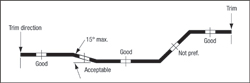 |
| Fig. 1 |
When a stamping is formed in an irregular shape it sometimes becomes necessary to punch holes on an angle, especially when punching is combined with trimming operations (Fig. 1). There is a limit, however, to the punching angle; it should never exceed 30 deg. A common practice has been to limit piercing and punching angles to a maximum of 15 deg. to avoid the complex guiding and support systems needed to control punch, stripper and part deflection. When punching angles exceed 15 deg., it generally is less costly and more reliable to add an additional operation or use a cam.
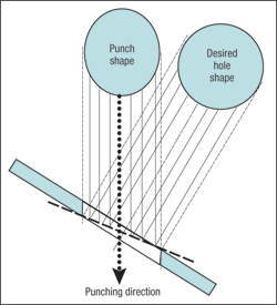 |
| Fig. 2 |
Hole-size accuracy is a common problem encountered when angular punching is employed. The punch cuts a hole opening in the part that is on a slight angle but the part print requires the hole size to be measured normal (perpendicular) to the part surface. As a result, the punch shape and size will differ from the final hole diameter. Graphical methods, similar to the one shown in Fig. 2, can be used to approximate the radii for a pierce punch at a given angle that requires the hole to be round on the face of the part. This is accomplished by creating a layout 10 times actual size.
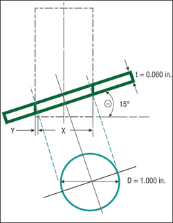 |
| Fig. 3 |
Hole-size elongations can be calculated rather easily and precisely, too. A method for calculating the hole elongation—we’ll call this the minor-axis punch diameter—for holes punched on an angle is shown in Fig. 3. For example: Find the minor-axis punch diameter (X+Y) if the part print hole-diameter specification is 1.000 in., the material thickness is 0.060 in. and the hole is being pierced at a 15-deg. angle.
Distance “X” is equivalent to the cosine of the cutting angle (15 deg.) times the punch diameter (D).
Cos. 15 deg. = 0.9659
D = 1.000 in.
X = 0.9659 in.
Distance “Y” is equivalent to the sine of the cutting angle (15 deg.) times the material thickness (t),/span>
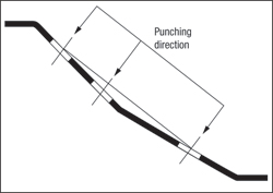 |
| Fig. 4 |
Sine 15 deg. = 0.2588
t = 0.060 in.
Y = 0.0155 in.
Calculation Results: Minor-Axis Diameter = 0.9659 in. + 0.0155 in. = 0.9811 in.
Final Punch Size = 0.9811 in. by 1.000 in.
The resulting hole shape is not perfectly round. Therefore, the punch and die matrix must be keyed to ensure proper alignment.
Cam-piercing operations may still require some of the punches to cut on an angle (Fig. 4). Again, keep the maximum punching angle less than 15 deg., calculate the minor-axis diameter and be sure that the punch body and die matrices are keyed. MF
