Peter Ulintz Peter Ulintz
Technical Director

Springback in High-Strength Steel Stampings "Compensation is Not Commensurate with Experience"

April 1, 2009
0
Comments


Springback, sidewall curl and panel twist all have their origins in unbalanced stresses in the formed part. These may be inherent in the product design due to nonsymmetrical geometry and cutouts, rapid changes in cross-section, or unequal flange lengths. They may be equally inherent to the forming operation due to the number of highly interactive process parameters. These include die-process lubrication, die-polishing techniques, blankholder forces, blank positioning, and broken or worn draw beads, just to name a few.

Some compensation for springback is routinely designed into most forming processes to limit or reduce the number of additional over-bending or restrike operations. The method and magnitude of compensation usually depends on the die designer’s experience with similar parts, materials and processes. The arrival of new higher-strength steels dramatically changes the old approach to springback compensation because previous experience with these new materials does not exist.

Today, simulation codes often are employed to study relationships between product geometry, die geometry, material properties, friction conditions and springback. The goal of springback simulation is to provide both compensation direction and magnitude for die tryout. But research has exposed several weaknesses relating to the accuracy of springback prediction in sheetmetal- forming simulations, especially when higher-strength steels are involved. For example:

• Springback results are shown to be very sensitive to anisotropy values (delta-r).

• Very different springback results have been observed when using different workhardening rules.

• Friction coefficients are shown to be highly influential in springback calculations.

• Material models that consider strain-rate sensitivity (m) values predict different springback magnitudes and modes than rate independent models.

With the increasing use of higher-strength steels and the inherent springback problems that come with them, recent research has intensified to achieve improved accuracy in both forming and springback predictions. Still, current springback results provide very useful data for die process planning and initial springback compensation.

Because springback is a major concern in higher-strength applications, it must be addressed as early as possible in the design phase. Springback can be minimized in the product design phase by:

Avoid right or acute angles
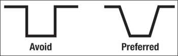
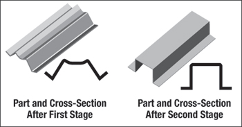
Fig. 1—Avoid right or acute angles when forming higher-strength steels.

• Avoiding right or acute angles (Fig. 1).

• Using large open-wall angles to allow for over-bending and springback.

• Avoiding large transition radii between two walls.

• Using opened-end stampings instead of closed-end stampings.

• Using stiffeners, darts, step flanges, etc., to prevent the release of elastic stresses.

• Designing punch radii as sharp as formability and product design will allow. Radii less than 2t will help reduce springback angle.

A well-planned stamping process also can minimize springback magnitude and part-to-part variability. Because steel work-hardens as it is pulled over a die radius, the resulting higher strength causes increased springback and side wall curl that can make restrike operations difficult. To achieve the desired channel height while limiting material movement across any radii, the hat section channels in Fig. 2 also can be formed using a

Sidewall curl
Fig. 2—Sidewall curl in higher-strength steel channel as compared to HSLA. Courtesy of International Iron and Steel Institute (IISI).
two-step approach known as the gull-wing process.

The gull-wing process is a multiple-step forming process that can improve part-geometry control as compared to single-step forming processes (Fig. 3). In the first step, all 90-deg. radii and mating surfaces are formed with the required over-bending for springback compensation. Flattening the large radius on top of the hat section takes place in the second operation, which may require additional over-crowning of the flat top section in order to produce parallel walls.

Not all product geometry lends itself to the gull-wing process. When drawing over a draw-die radius is the only practical forming method, post-stretching the side walls of the stamping after forming is an option. In this process, the part is placed into a second tool that is designed to lock out the remaining draw flange. A lower pressure pad with lock beads is designed to engage the sheetmetal blank and upper-die steels approximately 6 mm or less from the bottom of the press stroke. The lock beads prevent material flow into the die cavity and the part is subsequently stretched over

Two-stage forming process to create hat-section with small radii
Fig. 3—Two-stage forming process to create hat-section with small radii.
the post. The resulting stretch (about 2 percent) in the part usually proves effective in reducing residual stresses and part-to-part variations. Keep in mind that a lower lock-down device will be required to avoid deforming the part on the upstroke due to the opposing pressure pads.

Similar results may be achieved by using active (movable) draw beads in the draw die. Under certain conditions, this approach may eliminate the need for a secondary post-stretch operation. For more detail, refer to the draw forming section in the feature article beginning on page 16.

Another method used to reduce and control springback in draw dies includes employing variable-binder-force controls. In this process, the pressure profile for the binder varies throughout the punch stroke. Other binder technologies include pulsating blankholders and flexible blankholders.

Adding stiffeners, darts, step flanges and other embossments can help prevent the release of elastic stresses and reduce springback variablilty. Work with your customer to incorporate these features where part design allows. MF

Industry-Related Terms: Blank, Die, Draw, Drawing, Flange, Forming, Stroke, Twist
View Glossary of Metalforming Terms

Technologies: Lubrication, Materials, Tooling

Comments

Must be logged in to post a comment.
There are no comments posted.

Subscribe to the Newsletter

Start receiving newsletters.