FLC0 = n/0.21* [23.3+(14.2* t)]
= 0.18/0.21* [23.3+(14.2* 0.8)]
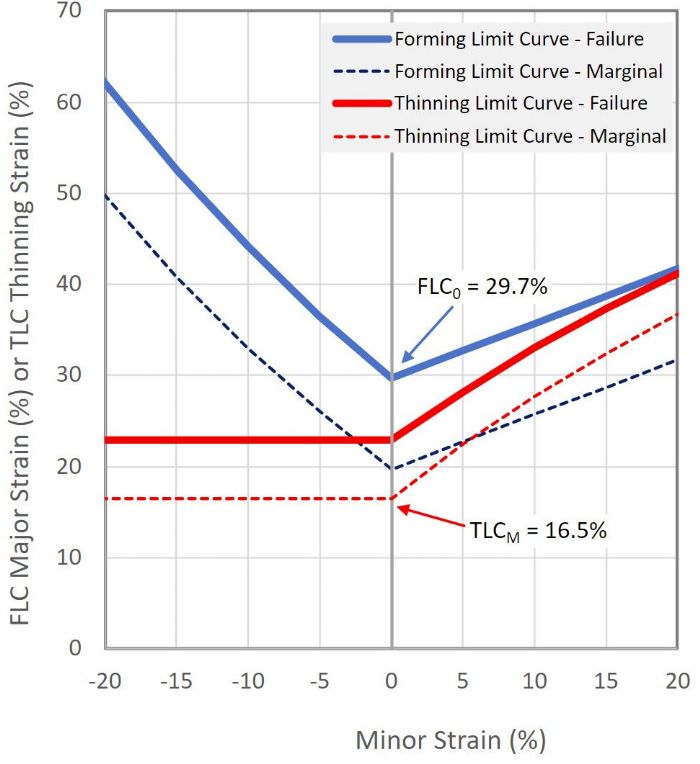
= 29.7 percent
When stamping materials other than low-carbon steels, determine FLC0 as the lowest point on the FLC provided by the material supplier and use it in subsequent calculations.
Traditionally, subtracting 10-percent major strain from FLC0 accounts for the safety margin. The lowest point on the marginal FLC in this example is:
FLCM = FLC0-10 percent=19.7 percent
The laws of physics must be maintained, even with sheet metal deformation. A unit of material must maintain a constant volume before, during and after forming. This allows calculation of the thickness strain (et), as the major strain (eMa), minor strain (eMi) and thickness strain in that unit of material multiplied together must equal 1:
(eMa +1) * (eMi +1) * (et + 1) = 1
Or, rearranging for thickness strain,
et = 1/[(eMa + 1)*(eMi + 1)] -1
The failure thinning strain is the through-thickness strain before the onset of necking failure. Calculate the failure thinning strain under plane-strain deformation using FLC0 as the major-strain value and a minor-strain value of zero:
TLC0 = etf=1/[(FLC0+1)*(0+1)]-1
= 1/(1.297*1) - 1
= 0.771 - 1 = -0.229 =-22.9%
For steels, this equation applies to both draw and plane-strain deformation.
TLC0—the border between the marginal and failure thinning strains—is based on FLC0 as described above. Similarly, the border of the safe and marginal thinning strains of the thinning limit curve (TLCM, where M represents marginal) is based on FLC0 minus 10 percent:
TLCM=etM=1/([(FLC0 - 10)+1)] *(0+1))-1 = 1/(1.197*1) -1 = 0.835-1 = -0.165 = -16.5 percent
Critical Thinning Calculation
In the example above for 0.8-mm low-carbon steel with an n-value of 0.18, the failure thinning strain is -22.9 percent. Reducing the starting thickness by 22.9 percent results in a sheet 0.617 mm thick. This indicates that any areas in plane strain on the formed part measuring 0.617 mm or thinner likely will split in production.
In this same example, the marginal thinning strain is -16.5 percent. Reducing the starting thickness of 0.8 mm by 16.5 percent results in a sheet 0.668 mm thick. So, any areas in plane strain on the formed part measuring 0.668 mm or thicker can be considered safe in terms of formability. Thickness measurements between these two values indicate that the measured area is in the marginal zone of the FLD, which highlights regions of the part that may become problematic when die conditions deteriorate, lubricant coverage changes or when sheet metal surface properties change—such as roughness, peak count, waviness or zinc-coating weight.
The calculated values in this example may have been the origin of the 20-percent rule of thumb, where the recommended maximum thinning of a formed part should not exceed a 20-percent reduction from the initial flat-blank thickness. The rule first gained use in the early 1990s, when 0.8-mm low-carbon steels with an n-value of 0.18 were commonly used for automotive body panels. Although not exact as determined from the equations, using a value of 20 percent may be a reasonable approximation if the practitioner wanted to avoid the calculations associated with the exact n-value and thickness of body-panel materials.
Where Not to Use the Rule
This approximation becomes less useful when stamping materials other than mild steel. For example, ultra-low-carbon steels have n-values closer to 0.25, which translates to an FLC0 of around 42 percent. This FLC0 also proves appropriate for austenitic stainless steels.
Using the above equations:
- FLC0 = 42 percent
- FLCM = 32 percent
- TLC0 = 29.6 percent
- TLCM = 24.2 percent
Using an arbitrary 20-percent cutoff, when 24.2 percent is instead the appropriate threshold, can lead to costly and misdirected decisions. For example, let’s assume an area on a part formed from 0.8-mm ultra-low-carbon steel sheet that is 0.615 mm thick, or a 23-percent reduction from the initial thickness. According to the 20-percent cutoff, this is an unsafe area likely to split in production. To avoid this possibility, shops may initiate die work or change lubricants; any option pursued will involve some combination of time and money to ensure a robust stamping process. But in cases where using a 20-percent cutoff occurs solely for the sake of simplicity, spending unneeded time and money just to avoid some calculations appears to be a foolish tradeoff.
There is a sound engineering reason for some maximum allowable thinning, but that relates to fatigue during the life of the part. Depending on the application, the alloy and the environment, a 20-percent maximum threshold may be reasonable to ensure structural durability. However, this requirement is completely unrelated to sheet metal formability concerns. MF
Note: Schaeffler will be speaking about higher-strength steels at the PMA/MetalForming magazine Metal Stamping and Lubrication Technology Conference in Cincinnati, OH, Jan. 18-19, 2022.
Technologies: Materials


 When it comes to taking the right steps to ensure a robust stamping process, the preferred approach is to conduct a surface-strain analysis generating a forming limit diagram (FLD). For most steel parts, the forming limit curve (FLC) should be based on the minimum allowable thickness and either the lower mill production limit or the minimum value allowed within the relevant material specification for the strain-hardening exponent (n-value). We should use the FLC provided by the material supplier for parts made from advanced high-strength steels, aluminum alloys or stainless-steel grades.