Stamping Aluminum
Most press-shop equipment used to form steel will suit stamping of aluminum. However, die-design rules primarily developed for steel must be modified for forming aluminum alloys. Critical process variables include:
• The formability characteristics of the aluminum blank;
• The geometry of the part and tooling, and
• Press setup, including lubrication and accurate control of blankholder pressure.
Aluminum forms a thin natural layer of aluminum oxide on the sheet surface that can break down during forming and abrade cutting and forming tools. This oxide film, very hard, brittle and tightly adhering, tends to break. This allows highly adhesive metal-to-metal contact, often requiring surface treatments (PVD, TD or other) to protect the tooling.
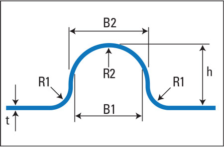 |
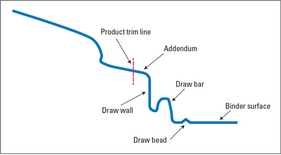
| Fig. 3—Draw-Bead Profile |
Due to the lower formability of aluminum compared to steel, product design features such as radii, draw depths, wall angles, steps and transitions must be carefully selected as they all interact to affect cost and quality when stamping aluminum . Engineers must design aluminum stampings carefully, especially if the components previously were produced from steel, to account for aluminum’s different properties. Because aluminum has one-third the elastic modulus of steel, the stiffness of an aluminum product previously produced from steel will be significantly less unless the product design is modified. The designer has two options for stamping aluminum: Increase sheetmetal thickness, or increase the number of ribs and stiffeners used in the product. The final stiffness of the aluminum stamping tends to increase in proportion to the square of its thickness, while the ribs increase stiffness by increasing cross-sectional area.
Also, the engineer must carefully specify part radii when stamping aluminum . Small radii can localize strains that promote stretching, and the part may fail quickly during forming. Conversely, large radii reduce the contact area between the blankholder and the part flange, increasing the tendency to form wrinkles in unsupported regions near the die radius. Difficult and irregular-shaped parts usually require addendum features to promote material flow and minimize localized stretching. The ultimate aluminum-stamping design will stretch evenly and distribute strains uniformly when deformed. Cup Drawing Cup-drawing ratio relates initial blank diameter to punch diameter. If this ratio is too large, the sheetmetal will not flow easily and may stretch extensively. Successful cup draws have minimal stretching because material displacement is primarily in compression. Draw-reduction ratios for cupping will vary depending on the aluminum grade and temper being formed. Some grades of aluminum can have a limiting draw ratio (LDR) similar to that of steel, while others will have a much lower LDR. Die-design handbooks usually contain draw-reduction tables for low-carbon steel. Due to differences in workhardening behavior, surface topography and other factors, engineers should not use these tables for brass, aluminum or other nonferrous metals. For aluminum alloys, engineers should aim for an LDR below 1.6, unless they have previous experience with the alloy being stamped. In general, start with a 40-percent blank reduction in the first draw, then 20 percent for the second reduction, and 15 percent for the third and fourth reductions [1]. Four or more successive draws have been performed on 1100, 3003 and 5005 alloys without the need for interstage annealing. The drawing reductions for higher-strength aluminum alloys (2014, 2024, 3004, 5052 and 6061, for example) will be somewhat less. The approximate amount of permissible reduction is 30 percent for the first draw, 15 percent for the second draw and 10 percent for the third. Local or complete annealing usually is necessary after the third draw with these alloys [2]. Draw-punch to die-cavity clearance generally is 110 percent of material thickness per side for the first draw. For higher-strength aluminum alloys, a clearance of 115 to 120 percent per side may be required. Subsequent draws require additional clearance as additional material thickening occurs with each reduction. Drawing Rectangular Boxes In drawing rectangular or box-shaped parts, draw depth generally is limited to seven times any corner radius for radii 0.500 to 1.00 in., or 12 times the corner radii for 0.250 in. or less. Keep draw and the corner radii to a minimum of five times sheet thickness.
We suggest a punch-nose radius of nine to 12 times sheet thickness along the straight sides, and a minimum radius of 12 times sheet thickness in the corners. The die entry radius also should be nine times sheet thickness along the straight sides and nine to 12 times sheet thickness in the corners. A general rule: Punch radius should be equal to or larger than the die radius to reduce the tendency of the punch to penetrate the material. For products requiring multiple draw reductions, the deformed surface area coming out of the first draw operation must be equal to the total surface area in the final draw. If the surface area is too great, oil canning, buckling and wrinkling become major problems due to excess material. When the surface area in the first draw is less than the final product surface, tensile failures can result due to excessive stretching. Drawing Irregular Shapes In processes not purely deep drawing but instead combine deep drawing and stretch forming, engineers must control material flow under the blankholder. Common controls include blank shape, lubrication, draw beads, lock beads and blankholder force. Irregular-shaped product geometries often benefit from the use of addendum to improve material flow. Die designers add addendum features beyond the product trim line to assist material flow by balancing cross-sectional lengths of line and providing a constant depth of draw. Commonly used addendum features include draw walls, draw bars, material gainers, take-up beads, pillows and punch extensions (Fig. 2). Blank shape (profile) proves particularly important when deep drawing irregular shapes. While a rectangular blank may provide simplicity and low cost, the shape often will not maximize formability. Optimum or improved blank shapes can be developed through analytical methods (forming simulations) or by trial and error, and will vastly improve aluminum draw-forming processes. Keeping friction to a minimum, while controlling sheetmetal flow, is the key to successful deep drawing of aluminum. When forming aluminum, it is imperative to separate the sheetmetal from the die surface. Lubricants formulated specifically for aluminum-stamping operations provide a tenacious barrier between the die surface and the oxide film on the blank. With the proper stamping lubricant, the blank avoids intimate contact with the tool surface. Polyethylene (PE) or polyvinylchloride (PVC) plastic films can be applied to the aluminum surface to aid drawing and protect the surface finish. These films provide excellent lubrication with friction coefficient values below that of oil. PE often proves adequate for most purposes, while PVC may be required for severe draws and multiple forming operations. Unfortunately, both can be difficult to remove. Strive to carefully control blankholding force. Sufficient pressure is required to keep the aluminum sheet from wrinkling, but excessive pressure can force the aluminum to stretch in areas that should draw. Use draw beads (Fig. 3) and lock beads (Fig. 4) to provide additional restraining forces to avoid excessive blankholder forces. Draw beads restrict material flow into a die cavity, by acting like speed bumps to slow material flow into areas where more stretching is required. This produces a tighter appearance in the stamping. The Aluminum Automotive Manual (from the European Aluminum Association) recommends the following general design rules for draw-bead profiles: R1 = 3 to 6t; R2 = 6t; B1 = 12t; B2 =15t h = 6 to 10t (t = sheet thickness) The center of the draw bead traditionally is placed about 25 times the sheet thickness from the side of the draw die (punch opening line). Lock beads will completely stop material from flowing into the die cavity. All deformation will be stretching, ensuring a panel that is as tight as possible. The Aluminum Automotive Manual recommends the following general design rules for lock-bead profiles: R1= 3t; R2 = 2t; B1 = 12t; B2 = 15t; h = 6t (t = sheet thickness) The center of the lock bead is placed about 24 times sheet thickness from the side of the draw die (punch opening line). Large depths of draw are required for curved parts if drawn off of a flat blankholder. The long drawing distances combined with pressure profiles—the change in pressure vs. distance—generated by gas springs can limit the formability of aluminum panels. Developed—or curved —blankholders minimize the required depth of draw by pre-shaping the blank to conform to the general shape of the finished stamping as the die closes (Fig. 5). The objective of a developed blankholder, in combination with properly designed addendum: Provide a uniform draw depth, and evenly distribute strains, during forming to prevent excessive stretching and fracturing of the stamping. Bending and Forming Total elongation values are important in bending because bending strains relate to the tensile elongation generated along the outside surface of the bend. Aluminum alloys with negative m-values will have low values of total elongation when measured during the tensile test. Instead of deforming all the to normal fracture strains, the tensile sample begins to rapidly neck and fail as soon as the ultimate tensile strength is reached and the width neck activated. For similar strengths, steel will fail with total elongations of 40 to 45 percent, compared to aluminum values of 24 to 30 percent. Consequently, the experience gained with bending steel cannot be fully transferred to aluminum. For example, a formed hem in steel can be pressed closed, while hemming aluminum will require larger-radii bends due to aluminum’s lower total elongation. Therefore, metalformers opt for a special type of hem, called a rope hem, on aluminum (Fig. 6). Bending with counter pressure is accomplished by bending a flange while holding the material between a punch and pressure pad (Fig. 7). This restricts the formation of folds or wrinkles in shrink flank flanges and minimizes edge stretching and tearing in stretch flanges. The application of counter pressure also helps to reduce springback. Punching and Cutting Good cut-edge quality is required to avoid the generation of slivers or fine particles in the cutting stations. These slivers can carry through the downstream processes and damage the surfaces of formed parts. Excessive sliver and particle accumulation also can cause galling. Good cut-edge quality also is required to maintain formability of the free edge for subsequent forming operations. The quality of the cut edge relates directly to the alignment of the punch to the die cavity, and the clearance between the punch and die components. Cutting clearance usually is expressed either as a total clearance—the difference between the punch diameter and the die opening, or (most often) as a per-side cutting clearance. The proper amount of cutting clearance depends on material type, thickness and shear strength. In general, per-side punch-to-die clearance for aluminum alloys will be 3 to 8 percent of material thickness for lower-strength aluminum alloys (UTS up to 230 MPa); higher-strength alloys (UTS over 230 MPa) may require as much as 11-percent per-side cutting clearance. With proper cutting clearance, the fractures that develop on the top and bottom sheet surface meet cleanly without secondary shearing. Secondary shearing, also referred to as a double-break, indicates insufficient clearance. Conversely, excessive cutting clearances will cause the development of a large radius or dished contour at the shear edge, often accompanied by a large burr. The condition of the cut edge also depends on the sharpness of the tooling. Dull cutting edges on a punch or die will produce effects similar to those of excessive cutting clearance. The natural layer of aluminum oxide on the sheet surface can break down during forming and abrade forming and cutting tools. This leads metalformers to opt for cutting and forming tools manufactured from high-grade tool steels that often require an application of PVD, TD or other surface treatments. A light overall lubrication should als be applied to both sides of the aluminum sheet, even during blanking and shearing. MF References [1], [2] ASM Specialty Handbook: Aluminum and Aluminum Alloys
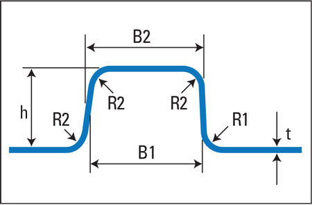
Fig. 4—Lock-Bead Profile
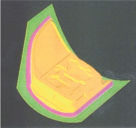
Fig. 5—A Curved Blankholder (Courtesy of Altair Engineering)
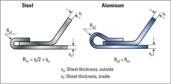
Fig. 6—Comparison of Hemming Geometries for Steel and Aluminum [3]
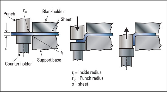
Fig. 7—Flanging with Counter Pressure [4]
View Glossary of Metalforming Terms