Share content on LinkedIn Share content on YouTube

Forming Aluminum Stampings—Part 1

March 1, 2009
0
Comments

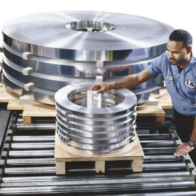
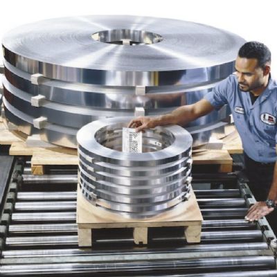
The benefits of aluminum for weight reduction and fuel savings in automotive applications have been well recognized for decades. The use of aluminum can reduce weight by 40 to 60 percent as compared to steel. The combination of low density, high strength and excellent corrosion resistance makes aluminum alloys attractive to the automotive industry and for thousands of applications outside the automotive industry. Recently, weight reduction and fuel economy have become greater foci among automakers, consumers and government regulators. As worldwide auto sales continue to lag, automotive-stamping suppliers are attempting to diversify by pursuing new customers in non-automotive markets. As a result, many contract manufacturers and tool and die shops accustomed to working primarily with steel stampings may find themselves confronted with aluminum products and their processes. Hopefully, the information presented here will prove helpful to anyone forming aluminum for the first time.

As a general comparison, it can be estimated that the formability of medium-strength aluminum is about two-thirds that of drawing-quality steel (Source: Aluminum Association, Publication AT3). The mechanical properties of aluminum differ significantly from that of steel and, therefore, it deforms differently during the stamping process. Clearly, aluminum stampings, their dies and manufacturing processes must be designed for the properties and characteristics of the aluminum alloy chosen for the stamping. Of primary concern are the material properties of the sheet, the geometry of the product, the geometry of the tooling and the press setup.

Material Properties

Aluminum has roughly 60 percent of the stretching ability of steel. Many automotive grades will form much like steel with 100,000-psi yield strength. Aluminum also has a thin natural layer of aluminum oxide on the surface. This hard oxide layer can be broken during the forming process and rapidly wear the forming tools. Consequently, tool-steel selection, heattreatment and surface treatments become very important. Furthermore, a light overall lubrication is required on both sides of the blank, even during blanking and shearing.

Aluminum also has one-third the Young’s modulus of steel. This reduction in Young’s modulus increases the likelihood for wrinkling, oil canning and other surface distortions. Although compensation for springback can be made in the stamping tools, the window between acceptable shape control and fracture is much less than that for steel. A successful aluminum-stamping die process combines good product design with good die designs.

Aluminum has a negative m-value, therefore, it has poor strain-distribution characteristics as compared to other materials with positive m-values, like steel. The ideal aluminum stamping design stretches evenly and distributes strains uniformly when deformed. The friction, die geometry, material properties and the forces restraining material flow into the die cavity combine to determine how the strain is distributed in a given stamping.

Product Geometry

Difficult and irregular-shaped product geometries

Limiting drawing ratio
usually require addendum features to promote better material flow and minimize localized stretching. Because of its planar anisotropy and forming limits, aluminum-sheet forming also is highly dependent on the shape of the blank. The part design, including radii, draw depths, wall angles, steps and transitions all interact to affect the cost and quality of the aluminum stamping.

Select part radii carefully. Small radii will localize strains and promote stretching and the part will fail quickly. Large radii reduce the contact area between the blankholder and the part flange. This increases the tendency to form wrinkles in the area near the die radius. Punch radii for aluminum stampings tend to be 8 to 10 times the material thickness while die radii range from 5 to 10 times material thickness. It is important to note that the punch radius should als be larger than the die radius to reduce the tendency for the punch to penetrate through the material.

Tooling Geometry for Cup Drawing

Drawing ratio is the relationship between initial blank diameter and the punch diameter (illustration). If the draw ratio is too large, the material does not flow and may stretch extensively. Successful deep draws have minimal stretching because the displacement of material is primarily in compression. Forming aluminum works a lot like a tube of toothpaste: Squeezing (compressing) the tube forms a bead of paste. If one were to pull on the bead—placing it into tension—it would pull apart immediately. This occurs because toothpaste has no stretching capability. This analogy also can be applied to aluminum sheetmetal. For example, aluminum beverage cans are produced from full hard aluminum blanks, which have practically no stretching capability. The manufacturing process includes cupping, redrawing, ironing and necking. All are compressive forming modes.

Proper blank size is extremely important for aluminum products. The area for the first draw must be equivalent to the area in the final draw reduction. If the area is greater, oil canning, buckling, and wrinkling become major problems due to excess material. If the area of the first draw is less than the final draw, tensile failures result due to stretching.

Draw-reduction ratios will vary depending on the aluminum grade being formed. Some grades of aluminum can have limiting draw ratios similar to that of steel, while others have much less. When cup drawing aluminum alloys, keep the limiting draw ratio (LDR) below 1.6 unless you have previous experience with the particular alloy you are working with. An LDR of 1.6 is equivalent to approximately 38-percent reduction for the first draw. Subsequent redraw percentages should be approximately 22, 17 and 12 percent, assuming the ratio of material thickness to blank diameter (t/D*100) is 0.25 or greater.

Most die-design handbooks contain draw-reduction tables for steel. Due to differences in work-hardening behavior, surface topography and other factors; these tables should not be used for brass, aluminum or any other material.

Next month we’ll discuss tool geometry for drawing boxes and irregularly shaped aluminum stampings. MF

Industry-Related Terms: Brass, Corrosion Resistance, Die, Draw, Drawing, Flange, Form, Forming, Layer, Oil Canning, Surface, Thickness, Wrinkling, Alloys, Aluminum Alloy, Aluminum Oxide, Blank, Blanking
View Glossary of Metalforming Terms

Technologies: Materials, Tooling

Comments

Must be logged in to post a comment.
There are no comments posted.

Subscribe to the Newsletter

Start receiving newsletters.