


Are Simulative Tests Still Useful?
August 1, 2016Comments
Decades ago, simulative tests served as a main source of information defining how different metal alloys would survive forming operations based on part shape and complexity. Virtual forming-simulation software, computer-controlled tensile-test machines, lubricant evaluators and other equipment used today were not available. Instead, small test devices were created, most of which were developed overseas. Some common tests: the Fukui conical cup test, Swift cup test, Olsen dome test and 4-in. hemispherical-dome test. The resulting data proved very useful when comparing different types, grades and surface finishes of materials tested on the same small device.
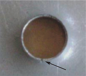 |
| Fig. 1—A hole expansion test (HET) made with a hemispherical punch. The arrow points to the start of an edge tear that terminates further expansion. |
One important simulative test still widely used in North America is the hole-expansion test (HET). It characterizes material stretchability to help judge a stamped part’s susceptibility to edge cracking—a major concern with most parts. During shearing to create an edge on the sheetmetal, large amounts of cold work greatly reduce the material’s stretchability. This loss of stretchability can extend one-half material thickness back from the cut edge. Dull tools, improper alignment, angle of cut, clearance, mechanical properties and other process variables can further reduce the allowable stretch.
To conduct an HET, the operator punches a hole into the production material using (as closely as possible) the press conditions that match those in production. He then places the sheet on the die; draw beads lock it in place. A tapered punch (conical or hemispherical) then is driven through the hole to enlarge it until an edge crack occurs (Fig. 1).
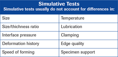 |
| Chart listing some of the differences between small test devices and actual full-sized production stampings. |
A forming-limit curve (FLC) cannot predict the onset of the edge cracking. Contrary to the belief of many users, nothing is wrong with the FLC. The error is created when the n-value of the as-received sheetmetal is inserted into the equation for FLC0. Instead, the very low n-value in the highly workhardened edge should be used. This substantially lowers the red-zone line. Even worse, a single representative n-value may not be found.
The second important test is the limiting draw ratio (LDR), used to define the maximum depth of a deep-drawn container or can. A blank is placed over a die consisting of a cylindrical opening and an upper and lower blankholder. A flat-bottomed punch contacts the blank and pushes it into the cylindrical opening, drawing material from the binder into the body of the can. The amount of available blank determines the depth of the container.
View Glossary of Metalforming Terms
Technologies: Materials, Quality Control
Comments
Must be logged in to post a comment. Sign in or Create an Account
There are no comments posted. Materials
Custom-Rolled Aluminum Coil and Full Metallurgical Staff
Thursday, June 5, 2025
 Materials
Novelis Tests Industrial-Scale Use of Hydrogen in Aluminum-R...
Friday, February 28, 2025