 |
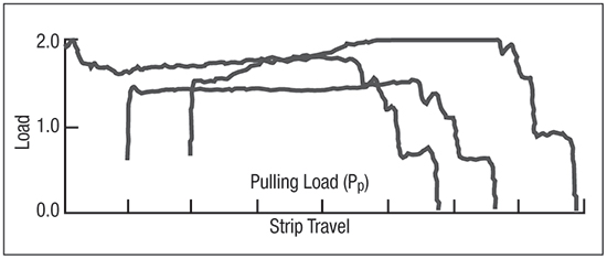
| Fig. 2—The fixed beads of the DBS are cleaned, polished and cleaned again. Three test strips are cleaned. No lubricant is used to create dry-to-dry testing; no COF can be calculated. |
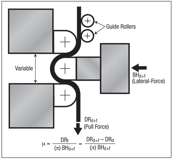
We use the DBS to conduct two sets of tests for each material/ lubricant combination. We begin by pulling three identical strips of material through the fixed-bead tester with pull and lateral forces measured to provide the load for repeated bending and unbending deformation, plus friction. Then we replace the fixed beads with frictionless (roller) beads to determine bending and unbending deformation only. The equation in Fig. 1 shows the coefficient of friction (COF) obtained by subtracting the deformation-only measurements from the deformation + friction measurements.
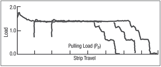 |
| Fig. 3—The test in Fig. 2 is repeated with a very thin layer of flex rolling oil as the reference lubricant. Excellent COF data can be obtained. |
Stamping of galvanized steels can create extreme press-shop experiences. Some report that the galvanized steels get stuck in the dies, lock up in the binder areas and seize on the punch. Others report the opposite behavior, with loose material, buckles and wrinkles due to a slippery work surface that makes the process difficult to control.
Therefore, the first DBS studies of galvanized steel established a baseline between bare steel and different zinc coatings that maximized the steel-tooling interaction. The most severe tests cleaned and dried the steel specimens and the beads. This dry test (Fig. 2) resulted in several problems. A reproducible, consistent and clean/dry condition is difficult to achieve. And, variations in clean/dry conditions occur between specimen strips and during the test of individual specimens. No COF values can be obtained.
To stabilize the test, we use a very thin layer of flex rolling oil as the reference lubricant. The oil eliminates the dry surface effects (Fig. 2) but does not hide the variations in surface friction (Fig. 3). The COF of steels coated with this reference lubricant are lower than with conventional mill oils. Among the interesting interactions observed (Fig. 3): the initial load spike for the first specimen tested after cleaning the beads. This spike is not due to the static versus dynamic COF—if that were true all three samples would show the same spike. The static versus dynamic COF can be observed in the small initial humps at the beginning of specimens two and three.
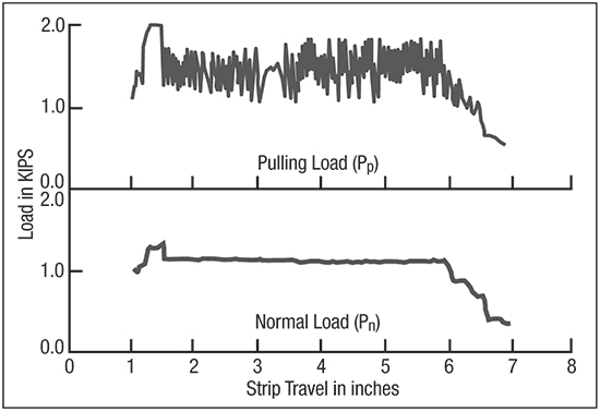 |
| Fig. 4—Even with sound lubrication, the galvanized-steel test specimen sticks and breaks a from the fixed draw beads. The stick-slip behavior does not affect the force driving the movable bead (lower graph). |
Further studies show the initial spike results from the transfer of zinc from the coated specimen to the freshly cleaned draw beads. After zinc transfer, all additional specimens tested without the beads being cleaned exhibit a constant load. This transfer is greater for soft hot-dipped zinc than for hard zinc-iron alloy.
Bare steel does not show this initial spike. The transfer is confirmed by scanning electron microscope (SEM) photographs that show a clean but lengthwise-scratched surface on the draw bead. After testing the first sample, the SEM shows globs of material adhering to the bead in a circular direction, due to the sliding specimen. An elemental map of the material shows the presence of zinc. Additional tests show that the height of the load spike decreases when using thicker lubricants.
One extreme result during the DBS studies is the stick-slip behavior of electrogalvanized steel tested with a good lubricant (Fig. 4). The sample tends to stick to the bead, release, then stick again, etc. The lateral force (identified in Fig. 1) holding the center bead is constant and does not show the load spikes. However, the test sounds like the screech of chalk being pulled across a blackboard. This stick-slip leads to galling of the die surface and then scoring. When the second specimen is inserted, it freezes to the draw bead in the first ¼ in. of movement. The test continues only by elongating the second specimen as a tensile sample until it breaks. Next month we will discuss press-shop applications and lessons learned from these and other metalforming tests with galvanized steels. MF Industry-Related Terms: Bending,
Blank,
Center,
Die,
Draw,
Layer,
Reproducibility,
Run,
Strips,
Surface,
TransferView Glossary of Metalforming Terms Technologies: Finishing, Materials