


Design for Manufacturing: Guidelines for Sheetmetal Fabrication
January 1, 2018Comments
Follow these tips to improve productivity and minimize, or eliminate, costly and wasteful engineering change orders.
 Perfect sheetmetal-fabrication designs—those that avoid engineering change orders (ECOs)—evolve only when designers take care to consider the capabilities of the equipment on the shop floor. For example, a designer may assume that hole and shaft diameter should match, thinking that a 50-mm-dia. shaft should fit into a 50-mm-dia. hole punched into a sheetmetal cover. However, the shaft will not fit into the hole; in fact, it will just sit on the circumference of the enclosure. To allow the shaft to sit on the hole seat, the hole and shaft both require dimensional limits and tolerances, based on the type of fit needed—clearance fit, interference fit or transition fit. In addition, when punching the hole, the tooling will create impressions on the sheetmetal, potentially leaving excessive burrs. This is one example of how reality can deviate from ideal conditions.
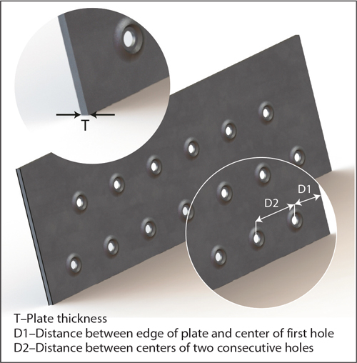
- Distance between two pierced holes, and between holes and sheet edges (Fig. 1)
When piercing several holes in a sheet, shear stress generated in the workpiece tends to reduce material strength. Even if the fabricator manages to punch the holes, part integrity will be less than ideal. To avoid workpiece failure, DFM guidelines recommend a minimum distance (D1) from hole to the sheet edge equal to at least the plate thickness (T); we recommend a safe design zone of 1.5 to 2T.
Also, when piercing multiple holes, we recommend a spacing between holes (D2) greater than 2T. This extra clearance between the tool and previously pierced holes will leave them unaffected.
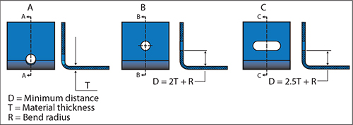
- Minimum distance between the bend and hole (Fig. 2)
When a workpiece is to be formed, minimum hole size relates to material thickness and bend radius. Maintaining a minimum distance between the bend line and the hole of twice the workpiece thickness plus the bend radius will avoid hole deformation during forming (Fig. 2A). Higher punching loads will cause the workpiece to undergo permanent deformation, reducing strength and load-carrying capacity.
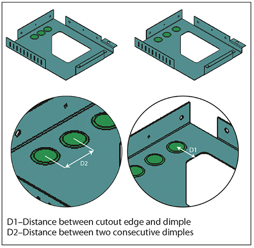
- Distance between two consecutive dimples, as well as dimples and cutouts (Fig. 3)
While assigning form features such as dimples on sheetmetal, fabricators must take care when assigning the features. Cutouts in the workpiece can cause the material near the dimples to fracture during punching. To avoid such fractures, maintain a distance (D1) between the cutout edge and the dimple of 4T plus the inner radius of the dimple. 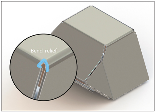
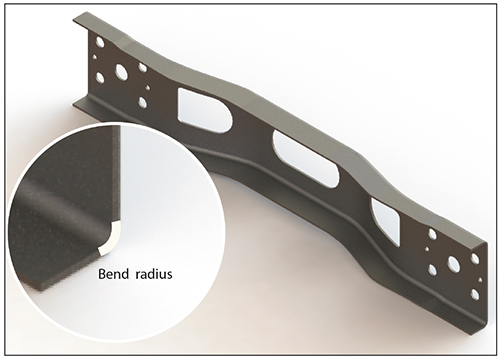
Fig. 4—Bend relief protects against edge tears. Fig. 5—Sufficient bend radius protects against excess stress.
Here, as with piercing, when the form station lacks sufficient clearance between the previously formed dimples and the successive dimple, the previously formed dimples can become flattened. To eliminate distortion, we recommend a minimum distance (D2) between two dimples of 4T plus the dimple radius.
Other DFM Features
Other DFM guidelines we recommend to sheetmetal-fabrication designers are those related to bend relief, to avoid the springback effect in the material. Overlooking the importance of these features not only will increase the number of ECOs but also will result in increased scrap and related costs. 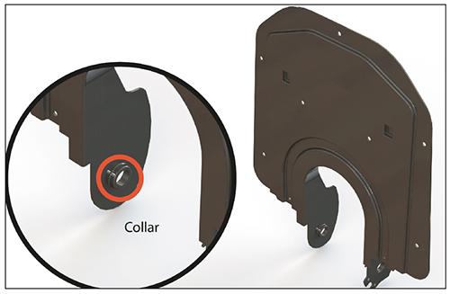
Fig. 6—Collars provide extra stiffness to the sheetmetal at flanges, especially near pierced areas.
Providing bend relief (Fig. 4) near the bends in the workpiece will avoid tearing at the edge of the material and also provide clearance to ease any downstream operations. In addition, providing a sufficient bend radius (Fig. 5) near the bends will ensure that the workpiece material does not undergo stress beyond its maximum limits and will not fail prematurely. Providing accurate bend-radius calculation also helps in reducing stress concentration near the bend.
Lastly, collars (Fig. 6) provide extra stiffness to the sheetmetal at flanges, especially near pierced areas. Collars will balance shear stress caused by the piercing operation. MF
View Glossary of Metalforming Terms
Technologies: Fabrication, Software
Comments
Must be logged in to post a comment. Sign in or Create an Account
There are no comments posted.
 Software
Sandvik Set to Acquire Verisurf
Tuesday, March 11, 2025
 Software
Interconnected MES Boosts Shop-Floor Control
Wednesday, February 26, 2025