 That emphasis on prototype development—some 50 percent of the firm’s work—leads me now to PTM’s Advanced Engineering Center (AEC), a dedicated facility focused on prototype development that houses its own set of hydraulic and mechanical presses (19 in all), two tryout presses, and a fully loaded fabrication area housing laser cutting machines and welding cells, including robotic welders.
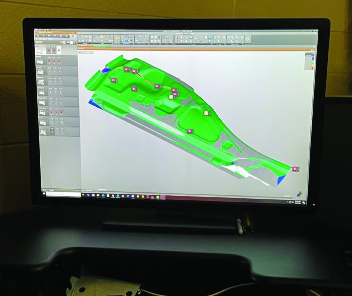 “Automotive prototyping ensures for our customers that the parts produced are functional,” Liggett says. “Our work allows our customers’ engineers to examine part performance in relation to other components and evaluate what might need to be changed or replaced.”
“We find that this extra time and technology spent in engineering up front,” adds Boghian, “has a trickle-down effect to the end of the process. From cutting the tools to inspecting finished assemblies, we save considerable time, effort and money. Better parts make for less qualifying and less time in the quality department, and better welded assemblies as well. AutoForm has been worth its weight in gold; without it we would not be able to predict what will happen in the press, especially with the higher-strength steels we’ve recently been working with, all the way up to 980-MPa advanced high-strength grades.”
Complex Geometries, “Wildly Shaped”
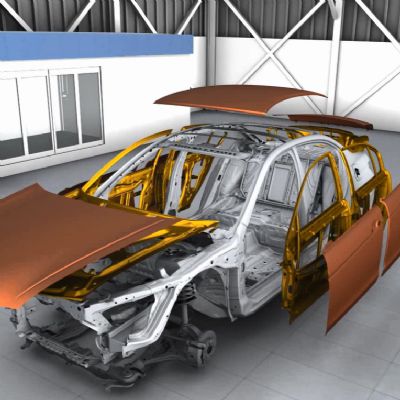
Geometry definitely has become more complex when it comes to developing prototype stamping dies, Boghian shares, often challenging him when asked to design tooling that can form parts that, otherwise, might be stamped as two or three separate parts and welded into an assembly.
 “A lot of prototype door-inner parts seem to be wildly shaped,” he says. “In fact, we’re developing a door inner right now where all of the reinforcements are very complex. I’m used to working with true radii and overall good geometry. But recently, I’m seeing designs that, rather than including blended radii, often feature surfaces in CAD mated without specified geometric properties—no radiuses, just a weird, formed shape. Luckily, because of my experience and the capabilities of AutoForm, I usually can go in and fix the surfaces to make them useful in die development.”
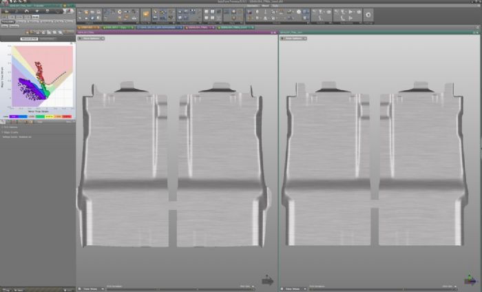 Once he started using AutoForm at PTM, Boghian took note of the software’s expanded capabilities, in particular its ability to take data from a 3D scan of a stamped part, created by the AEC’s quality department, and compensate the die design to make the part to spec.
“There aren’t too many companies using AutoForm in this way,” Boghian says, “but I find it very useful to take the actual output—the stamped prototype part—and go back into the tool design and reengineer it if needed. Typically, this occurs if the sheet metal properties don’t exactly match what our designs are based on.”
Modules, from Estimating to Springback Compensation
Among the several modules available in AutoForm Forming suite, PTM primarily uses AutoForm-Explorer, AutoForm-StampingAdviser, AutoForm-DieDesigner and AutoForm-Compensator modules, to plan and validate stamping processes and parts. The estimating department in the AEC uses AutoForm-CostEstimator to help estimate tooling costs early on in the planning and bidding phase with customers. The program calculates tooling costs based on a defined production sequence, allowing users to evaluate alternative production concepts.
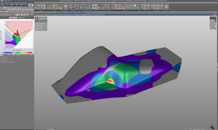
AutoForm-StampingAdviser enables Boghian, he explains, to quickly evaluate part and process feasibility for new designs coming down from customers, to perform springback analysis and compensation to help develop blank shape and evaluate material utilization.
“I can check and compensate for splitting and excess thinning,” he says, “as well as for the potential for wrinkling.”
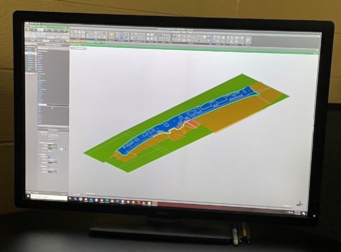
With DieDesigner, Boghian can use CAD part geometry to develop—and adjust—die-face designs, as well as create addendum and then automatically develop flanges on to the addendum surface.
“Then, using Compensator, I can modify the die surfaces based on precise springback calculations,” he says, “or measured springback, defining compensation regions or the complete surfaces.”
Explaining how PTM’s use of AutoForm-CostEstimator benefits customers, “before, when a design moved from estimating to production, it was basically just a picture of the part,” Boghian says. “We’d see, for example, that estimators calculated the need for a specific number of die stations, and would name each station (form, flange, trim, etc.), but the design was incomplete. Now with AutoForm-CostEstimator, they typically can go into the design and select specific part features and provide us with a more complete die-operational layout. The process design coming from an estimator is much more accurate station to station, simplifying what we have to do in design and ultimately allowing us to start producing the tooling much more quickly than before.”
No CAD Needed
Last but not least, PTM’s AEC has been an early user of AutoForm-DieDesignerPlus, which allows a designer to create part-geometry features within the AutoForm interface.
“I can use the software to quickly create CAD-quality die-face geometry without using a separate CAD system,” Boghian notes. “That can make the process very efficient. Theoretically, we can design an entire tool inside of AutoForm and not have to take any new surfaces created back into CAD to fix them. Now, we can go right from AutoForm and cut the tool, the surfaces are that good.” MF
View Glossary of Metalforming Terms
See also: AutoForm Engineering USA, Inc.
Technologies: Software
 Webinar