Transfer Performance Keys Productivity
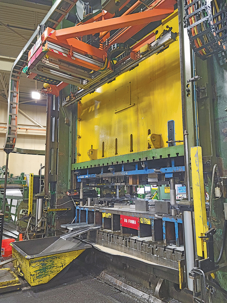
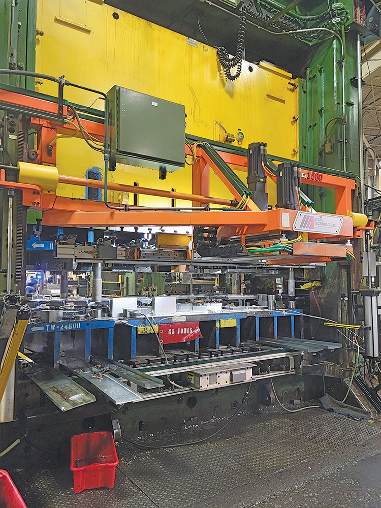
A key to meeting production and profit targets on volumes large and small involves transfer system performance, according to Siess. BAE houses two Atlas Technologies front-and-back three-axis electronic transfer systems. One, a Flex 1500 model on a 1200-ton 144-in.-bed press at the Warren plant, was installed in 2015; another works on a 2500-ton 240-in.-bed behemoth in Fraser, refurbished and added to production in 2017.
The high-speed programmable Flex 1500 can integrate with a new press or be retrofitted, and can transfer as much as 450 lb. of parts and tooling, offer Atlas Technologies officials, at stroke rates to 36 in. An overhead-mount design eases access to dies, with the bolster left open for scrap removal, and press windows clear for part-feeding equipment. And, jogging—forward and reverse, using a virtual press-simulation feature—acts independently of press actuation, allowing for cycling without the risk of die interference.
 Siess signed off on both Atlas Technologies’ transfer additions, owing to his experience on working with the supplier for more than 20 years.
“When I came to BAE, we had one transfer system inhouse already, dating to about 2004,” he recalls. “To be profitable in offload business, we needed to be a full-service supplier—running presses to 2500 tons and bed sizes to 240 in., which would allow us to function as a Tier-One contract stamper. As a result, we added the Flex 1500 transfer system on one of our 1200-ton presses here in Warren, and brought back a mothballed 2500-ton 240-in-bed press in Fraser. That press already had an Atlas transfer. We removed it and sent it to Atlas to refurbish during press install, and it came back six months later with state-of-the-art controls.”
This retrofitted system now can be considered a Flex 3000, according to David Kuch, Atlas Technologies account representative.
“In 2017 we upgraded the existing Flex 5000, which included both mechanical and controls refits,” Kuch explains. “When we upgraded the control system to our current Rockwell A/B platform on the Flex 5000 chassis, we discontinued the original Flex 5000 model designation in favor of the Flex 3000.”
With transfer systems inhouse and serving production needs, Siess, with his team, doggedly sets about to ensure their effectiveness. Effective transfer system operation at BAE rests with three core beliefs espoused by Siess:
- Front-and-back is ideal
- Optimizing motion is king
- Opt for universal tooling.
Front-and-Back is Ideal
“Front-and-back transfers have tremendous flexibility and structural advantages over other types of transfers,” says Siess, “starting with the ability to switch from progressive-die to transfer-die mode and back in 3 min. or less. And, moments of inertia and bending moments in a front-and-back system allow for higher speeds, and the system offers a far more mass-efficient structure. Everything about it is a win. The drives are smaller, but the transfers run faster, with less bounce.”
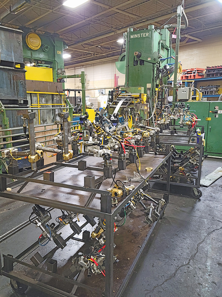 Consider, for example, a transfer system for a 240-in.-bed press.
“The longest transfer component in a 240-in.-bed transfer press at our facility is the universal transfer rail, and in supporting that, no member is longer than 4 ft.,” Siess explains. “In that same press, a through-the-window transfer system has 30-ft.-long beams, with all of the moment-of-inertia and bending-moment issues, as well as the large drive sizes necessary to handle the increased mass, and all of the bounce that transfers to the finger tooling.”
Optimizing Motion is King
A common belief: The shortest distance between two points is a straight line. But, transfer systems can’t operate in a straight line.
“In transfer applications, the shortest distance between two points is the top half of a horizontal ellipse,” Siess offers. “The only two fixed points in a transfer application are the beginning of the transfer distance and the end. Everything else, we have freedom to program in accordance with minimizing acceleration and deceleration The transfer programming targets the top half of a horizontal ellipse, and that’s what we shoot for. We need to optimize the travel path and maximize corner rounding.”
Optimizing that path, Siess explains, involves a number of steps:
- Bring the finger tooling in at the earliest possible point. “That means trading paint with the upper die shoe,” Siess says, “knowing where the first crash will come and traveling just short of that—almost clipping it on the way in.”
- Understand the difference in time and location from telling something to move, and it actually moving. “In every transfer system that I’ve seen, the torsional wind-up in bars, the actuation of solenoids and everything else, has 8 to 10 deg. of lead time. That must be figured into the transfer programming.”
- Exit at the latest possible point. “A three-axis transfer has six motions: forward and reverse on three axes—clamp in and out; lift up and down; transfer forward and reverse. Three of these transfer motions occur without a part; run those motions as quickly as the drive will allow. The key is what occurs while the parts are in contact with the finger tooling. Maximize the amount of time that the transfer's in contact with the part and minimize the time when it's traveling back to its home position without a part. When we have a part in the fingers, we have to use TLC. In sum: Three motions should get all of the attention in programming, then take the space that is left and run like heck to get back to home position for next stroke.”
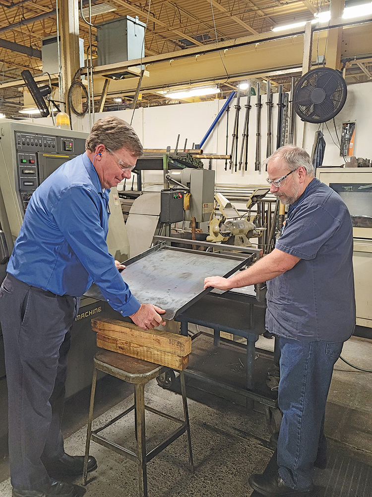 These programming tips paid off big time in optimizing an older transfer system—installed in 2004—on a 240-in.-bed press at the BAE plant in Warren.
different program values—not changing a single piece of hardware, using the same drives and only optimizing programs—we went from running at 98-percent drive load at 11 strokes/min. to running at 70-percent drive load at 21 strokes/min., with a 48-in. pitch.”
Opt for Universal Tooling
“I am adamantly opposed to dedicated finger tooling,” Siess says, citing costs that can run to three times that of universal tooling, as well as flexibility. “All of our universal rail tooling has been through three, four or five reapplications, retrofitted for each new job as needed. When we finish using it on one job, we place it into a cabinet, then take it out and adapt it for another set of tooling. The universal tooling rails provided by Atlas Engineering really allows us to be flexible, and it provides a real advantage. Dedicated tooling just becomes obsolete when a job ends. I would push universal rails for anyone in contract stamping.”
BAE Industries maintains finger tooling at the ready for quick connection to rails as needed, making job changeover a rapid and efficient process.
“As a contract stamper,” says Siess, “we sell our ability to run a customer’s offload tooling in our presses. Universal rail tooling makes it much easier to do that.”
Inhouse Expertise Makes It All Work
From identifying productivity-enhancing opportunities to optimizing transfer programs to building and maintain tooling, BAE Industries has the inhouse expertise and experience to make it all work.
“We have a great amount of knowhow, an excellent machining and prototype area, some of the best tool and machine repair people in the world, and some brilliant mechanical engineers,” Siess offers.
Gaining from this expertise and experience: Atlas Technologies, with the communication loop resulting in a mutually beneficial relationship.
“Feedback from Brian Siess and BAE has helped us evolve and fine-tune what we offer,” says David Hense, Atlas Technologies president, “while our systems and components serve BAE Industries well.”
Inhouse capabilities at BAE allow for solutions to myriad challenges on the plant floor. For example, issues with feedstock buckling in progressive-die applications led to an inhouse-designed and -built mechanism to support the stock as it exits an electronic roll feed. It reduced buckling by as much as 90 percent and reduced miss-hits by a like amount, according to Siess.
And, beyond transfer optimization, BAE proactively addresses other areas as well.
“We have our Press Optimization Team process,” Siess explains. “It involves understanding the 360 deg. of standard mechanical press motion, and making sure that we’ve optimized every single degree in that 360 deg. We explore how to achieve maximum speed and material feed by minimizing acceleration and deceleration, and how to use every bit of the press window available for accurate feed, pilot release and everything else. This has allowed us to increase speed on our presses by 60 to 70 percent.” MF
View Glossary of Metalforming Terms
See also: Atlas Technologies, Div. of Stonebridge Technical Enterprise
Technologies: Pressroom Automation, Stamping Presses, Tooling



 In addition to the Warren plant, BAE, under the direction of sole proprietor Jesse Lopez, operates a 40,000-sq.-ft. satellite stamping facility in Fraser, MI, and a 120,000-sq.-ft. main assembly facility in nearby Auburn Hills. And, warehouse operations in Silao, Mexico, support customers there.
 Video
Video