Jim Ward Jim Ward
Manager of Manufacturing

The Basics of Coil Processing Equipment, Part 2: Straightening the Coil

June 1, 2012
0
Comments


The purpose of straightening in a typical coil-feed line is to prepare the material to allow it to pass freely through the die and produce acceptable parts. Requirements vary depending on any material defects, the design of the die and finished-part requirements. Straightening is accomplished by bending the strip around sets of rollers that alternately stretch and compress the strip’s upper and lower surfaces, exceeding material yield point so that both surfaces end up the same length after springback. The result: flat material.

Types of Straightening Machines

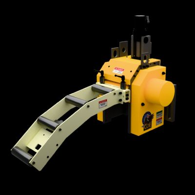
Straightening machines fall into two basic categories—straighteners (or flatteners) and corrective levelers. Straighteners typically operate five to 11 work rolls whose diameter and center distances vary depending on workpiece-material thickness and width. Generally, rollers are fairly large in diameter, widely spaced and not backed up. Straighteners will remove coil set from the material, allowing it to pass unrestricted through the die and satisfying most applications.

Corrective levelers will remove not only coil set but also camber, wavy edges, center buckles and trapped stresses within the material, so that it will stay flat after processing through a die. These machines are distinguished by small-diameter closely spaced rolls—with backups—and the ability to flex the rolls. They normally have a greater number of work rolls than conventional straighteners, and since they work the material much harder and their rolls can be flexed, precision levelers als are powered. Therefore, they require more powerful drives than do straighteners.

 
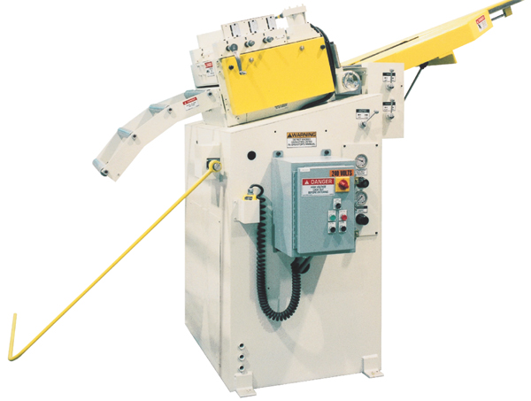
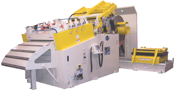
Power straighteners can be configured as part of the unwinder, as in the case of coil cradles, or for pull-off operation with coil reels. They also can be free standing with a second slack loop between the straightener and unwinder—as with pallet decoilers or in cases where delicate material would be damaged by pulling off of
a large coil.
Straighteners, on the other hand, can be powered or nonpowered—called pull-through straighteners. As the name suggests, here the feed provides the power to pull the strip through the straightener. The advantages of this style: low cost, and, since the straightening operation occurs after the loop, loop length can be condensed without the worry that coil set will be reinduced into the material.

With pull-through straighteners, horsepower must be drawn from the feeder. This can either reduce its speed capability or greatly increase cost. Additional disadvantages to pull-through straighteners include material marking, should the nonpowered straightening rolls slip on the material during starts and stops; and inaccuracy from feed slippage, due to the additional load.

Power straighteners or levelers can be configured as part of the unwinder, as in the case of coil cradles, or for pull-off operation with coil reels. They also can be free standing with a second slack loop between the straightener and unwinder—as with pallet decoilers or in cases where delicate material would be damaged by pulling off of a large coil. In most cases, a slack loop follows a powered model, which allows continuous operation without starting and stopping. This reduces power requirements relative to combination feeder/straighteners, which straighten material as it feeds and are required to start and stop with each feed progression.

Principles of Straightening

In theory, three staggered rolls should be sufficient to straighten most materials. This basic approach can be applied if the amount of coil set in the material remains constant throughout the coil. However, coil set can dramatically increase as the coil is depleted, depending on material thickness, composition and yield strength.

In most cases, coil set is induced in the material during a previous process, such as slitting, edge conditioning or finishing. The coil’s wraps are placed under tension and compression as the material bends around the outside diameter of the coil. Coil OD typically is 54 to 72 in., while the diameter of inner wraps around the inside diameter of the coil typically measures 16 to 24 in. This potentially large difference can result in a dramatic change in the amount of coil set in the material. With only three staggered rolls, the operator would have to constantly adjust the straightening machine to obtain an acceptable level of flatness.

Therefore, power straighteners are built with multiple work rolls to effectively address the issue of varying coil set. The more work the greater the ability to remove coil set.

Another basic principle of straightening: Thicker materials require fewer and relatively large-diameter rolls, with greater spacing between them. As material thickness increases, roll diameter and support-journal diameter must increase. Also, the work rolls must be able to withstand the forces required to back-bend the material without excessive deflection across their width.

Thinner materials will require a greater number of relatively smaller-diameter rolls, with spacing relatively short to effectively stretch and compress the material. On light-gauge material, consideration must be given to the support-journal diameter of the work rolls. As the width of the material and machine increases, so does the tendency for the smaller-diameter rolls to flex and deflect. This deflection of the straightening roll or journals can lead to material defects such as wavy edges, and machine problems such as broken journals and excessive gear wear.

Considerations in Equipment Selection

The modern metal stamper must build capacity and flexibility into his coil-processing and stamping machinery to meet the challenges presented by evolving product lines and new customers and markets. These overlying challenges present a substantial obstacle when specifying a new straightener. The stamper faces fundamental decisions early in the game related to the ability of the straightener to handle a variety of applications.

 A heavy-duty straightener (shown) with seven 4-in. dia. work rolls located on 7-in. centers will straighten ¼-in.-thick cold-rolled steel, but will have minimal effect on 0.050-in. cold-rolled steel. Likewise, a straightener designed with seven 3-in.-dia. work rolls located on 5-in. centers will effectively straighten the 0.050-in.-thick steel but will lack the horsepower and roll strength to process ¼-in. material.
For example, a straightener with seven 4-in.-dia. work rolls located on 7-in. centers, and given adequate power and gears, will straighten ¼-in.-thick cold-rolled steel. The same machine will have minimal effect on 0.050-in. cold-rolled steel. Likewise, a straightener designed with seven 3-in.-dia. work rolls located on 5-in. centers will effectively straighten the 0.050-in.-thick steel but will lack the horsepower and roll strength to process ¼-in. material. If an application calls for this type of variation in material thickness, a fundamental decision must be made in regards to the cost effectiveness of building a special machine to meet the full spectrum of needs, versus building a standard machine that will provide optimum straightening at either the light-gauge or heavy-gauge end.

Stampers also must consider the maximum width of the material and machine, and the range of material thicknesses to be processed. As straightener width increases so does the tendency for work rolls and journals to deflect under load, thus impacting the machine’s ability to process material with a defined thickness and width. This deflection can result in a loss of contact-surface area, decreased straightening efficiency, material slippage or broken work rolls.

Note: Do not request a machine capable of processing wide material without considering the effect that narrower material will have on the machine. A machine rated to straighten 48-in.-wide by 1⁄8-in.-thick steel may struggle to process the same thickness of steel, but as 12-in.-wide strip. The cross section and strength of the 12-in. material is substantially less than the 48-in. material, but the straightener rolls most likely will experience a greater amount of deflection when running the narrower material, as the forces and stresses are concentrated at the roll center. This area is furthest from the end journals and bearings that support the rolls. (A single row of backup rolls would allow the machine to efficiently straighten the narrower material.)

Horsepower Requirements

Although material thickness and width are fundamental, many additional factors impact the amount of horsepower required, including material yield strength. Most straighteners are rated by their capacity to process mild steel with less than 50,000-psi yield strength. Higher-strength materials will have a greater tendency to keep their coil set, demanding greater horsepower for straightening.

The combination of work-roll diameter and center-distance spacing can dramatically affect horsepower demands. For example, if two straighteners both have 3-in.-dia. work rolls and machine A has 5-in. center-distance spacing and machine B has 6-in. center spacing, machine A will require more horsepower to process material with the same thickness and width.

In a pull-off application, coil size and weight are critical variables in determining required horsepower. The maximum coil weight must be defined, since the straightener motor provides the torque and horsepower to accelerate the mass to line speed. The minimum and maximum coil outside diameter also must be defined. Though a coil has its greatest mass when at maximum outside diameter, this is not als the worst-case condition related to horsepower demands. As the coil is depleted, the straightener loses the mechanical fulcrum provided by the greater outside diameter, and its ability to overcome the drag-brake tension placed on the reel decreases. To address this issue, modern uncoiling systems include automatic drag-brake compensation.

The process requirements for throughput (in ft./min., or FPM) also are necessary to accurately calculate the requirements. To calculate required throughput, multiply the maximum speed of the press by the maximum progression length. For example, a press rated to 40 strokes/min. and a progression length of 18 in. generates a throughput of 60 FPM.

Note: Throughput often is established based on past or current production limitations, rather than on the potential of the equipment and tooling in the manufacturing process.

Achieving Maximum Effectiveness

Once a machine is specified and built, effective results depend on correct and consistent setup. The combination of pinch-roll pressure, drag-brake strength and work-roll depth setting will determine the effectiveness of the straightening operation. All straighteners use entrance-side pinch rolls to grip and pull the material; some also use exit-side pinch rolls to improve grip-and-pull capability. The amount of pinch-roll force required for a specific material depends on material width, thickness and surface condition.

Pinch-roll pressures typically are established by a combination air-pressure regulator and gauge. Heavy-gauge materials generally require greater pinch-roll forces, while thin materials tend to wrinkle under excessive pinch-roll force—which also can result in pinch-roll deflection and a loss of effective contact-surface area on the material, promoting slippage.

The drag brake maintains adequate tension on the strip between the reel and the entrance-side pinch rolls of the straightener. Optimum drag-brake strength varies with coil weight and outside diameter. When the coil is at maximum OD and there is insufficient drag-brake strength applied, the coil will tend to overspin and develop slack material between the reel and straightener. Eventually, the reel will decelerate and lose RPM due to the loss of tension in the strip. As the straightener continues to run, the slack is consumed and the strip will be snapped tight, possibly stretching or damaging the material. Excessive drag-brake strength, on the other hand, may cause material slippage through the straightener or lead to excessive tension on the material.

Establishing Roller Position

Most straighteners include a simple calibrated scale and pointer combination to establish roller position. The amount of work-roll penetration required to back-bend the material to an acceptable level of flatness varies with material thickness and type, roller diameter and roller center-distance spacing. With the optimum depth setting established for a specific material, the stamper must ensure that the work rolls return consistently to this position each time the job runs.

For those applications requiring more accurate positioning, digital roll-height indicators get the call. The upper work rolls of most straighteners are contained in precision-guiding slide-block assemblies. Methods for raising and lowering the rollers within the slide-block assemblies include fine-threaded screw and nut combinations, worm gear and screw mechanisms, and precision screw jacks.

Most often, coils are unwound from the top of the coil, so that the induced coil set naturally gives the material a downward bend. Stock straighteners typically are equipped with an odd number of work rolls, with the extra (or odd) work roll in the lower fixed bank of rolls. With proper setup, this configuration creates a slight upward bend in the material as it leaves the straightener, which helps the material slide across the die surface with a minimum amount of friction.

The guidelines for establishing proper work-roll depth settings tend to vary as much as the potential variations in material types, thickness and width. In addition, different machine builders recommend different setup practices for effective use of their machines. Here we’ll assume use of a seven-roll straightener with three adjustable upper work rolls. Position the first upper work roll to a setting that alternately stretches and compresses the upper and lower surfaces so that 60 to 70 percent of the material crosssection exceeds its yield point. Then position the second upper work roll so that 30 to 40 percent of the material crosssection exceeds yield point. Lastly, position the third upper work roll to bring the material back to a flat condition.

Use the least amount of roll penetration that produces an acceptable level of flatness. Excessive roll penetration will inhibit straightener efficiency, cause material to slip across the straightener, and place unnecessary strain on the machine’s drive components. To set roll penetration, conduct a quick visual check of material flatness before the material runs into the loop area. Then, using the threading table or similar device to support the leading edge of the material as it exits the straightener, fine tune work-roll settings to the minimum depth required to give the leading edge a slight upward bend. Document these settings for reference, to ensure the same setup is used each time the job runs. MF
Industry-Related Terms: Bending, Camber, Case, Center, Compress, Die, Edge, Gauge, Lines, Model, Pallet, Penetration, Point, Run, Scale, Spectrum, Surface, Thickness, Torque
View Glossary of Metalforming Terms


See also: Coe Press Equipment Corporation

Technologies: Coil and Sheet Handling

Comments

Must be logged in to post a comment.
There are no comments posted.

Subscribe to the Newsletter

Start receiving newsletters.