Where These Steels are Being Used
Several 2015 platforms are loaded with advanced steels; here are a handful of examples provided by the Steel Market Development Institute.
Acura TLX
To achieve the high rigidity that promotes a smooth and quiet ride, crisp steering and handling, safety performance and long-term durability, the TLX (Fig. 10) utilizes six different grades of HSS and AHSS in 52 percent of its body structure by weight. This high-grade, high-tensile strength steel adds the required rigidity for these positive traits without adding excessive weight, which in turn enhances fuel efficiency and lowers emissions. High-strength steel uses include:
• Hot-stamped HSS—Door opening rings, for five percent of the unit body
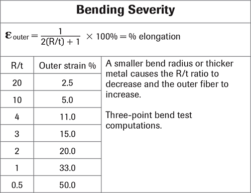 |
| Fig. 5—A small R/t ratio means higher percentage of outer fiber strain and a steel with a high percentage total elongation. |
• 980 grade—Key structural points such as the front edges of the door sills and in the A- and B-pillars, for two percent of the unit body
• 780 grade—Most structural load paths, including the side sills and forward spars of unit body, for two percent of the unit body
• 590 grade—Front frame spars, floor and roof supports, for 35 percent of the unit body
• 440 grade—Front bulkhead and in front and rear energy-absorbing structures, for five percent of the unit body
• 340 grade—Sheet steel used in the roof, for three percent of the unit body.
Chevy Colorado
In creating the Colorado (Fig. 11), GM engineers selected materials to optimize strength, safety and refinement of the truck while balancing dependability, cost of repairs and total ownership costs.
Like its larger Silverado sibling, Colorado extensively uses lightweight high-strength steels. Fully boxed frames formed primarily from high-strength steel reduce weight and increase stiffness.
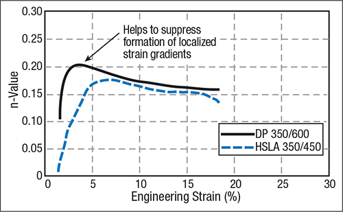 |
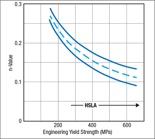
| Fig. 6—The higher initial n-value of DP steel helps to suppress early strain gradients. |
Key areas of the body structure also benefit from high-strength steels, reducing mass and enhancing strength and safety. Overall, about 71 percent of the body structure comprises high-strength steels.
The pickup box consists of rollformed steel, lighter and stronger than traditional stamped steel. AHSS grades find use for the rocker inner and outer, internal L reinforcements and section-stabilizing bulkheads. The B-pillar structure comprises an AHSS tailor-rolled-blank center-pillar outer as well as AHSS for the center-pillar inner, tension panel and local hinge reinforcements.
Ford Edge
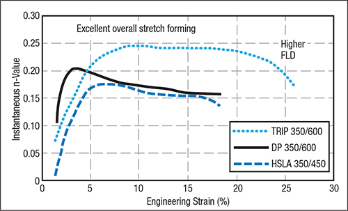 |
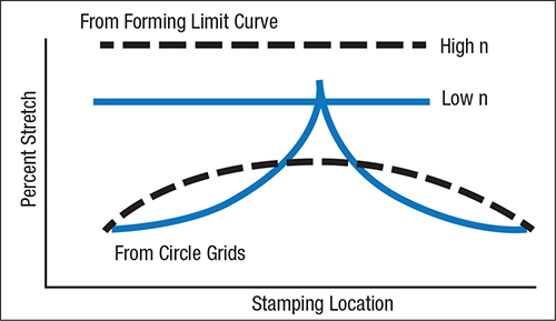
Fig. 7—The development of a 0.25 n-value allows a major increase in overall stretchability over HSLA and DP steels.
|
Thanks in part to the use of high-strength steels, the solid body structure of the new Edge (Fig. 12) provides a far better platform for the new suspension. Compared to the 2014 Edge, the new model shows a 26-percent increase in stiffness when reacting to bending forces and a 16-percent increase in stiffness when reacting to twisting forces.
Automakers haven’t finished tapping the potential of the new steels. According to a recent General Motors sneak-preview media release on the 2016 Chevy Malibu, the automaker claims to achieve a 300-lb. mass reduction in the redesign due to an HSS structure and a “blank slate approach.”
Tips for Forming AHSS
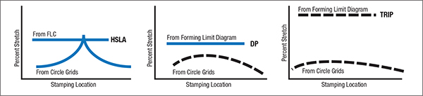 |
Fig. 8—How three 50-ksi yield-strength steels can modify the forming problems of initial peak strain and low forming-limit curve.
|
In general, the beneficial properties of higher strength steels—their high yield and tensile strengths and high ductility—also tend to degrade tool life and promote premature failures.
Tool-failure mechanisms common to higher strength steels include chipping, cracking and wear in punching, shearing and trimming operations. Wear and galling are predominant when forming higher strength steels. Tool wear can be characterized as either abrasive or adhesive. Abrasive wear to the tool typically is caused by friction. To reduce abrasive wear, stampers can increase the tooling material’s hardness or carbide volume. However, this will reduce the tool’s toughness and resistance to adhesive wear.
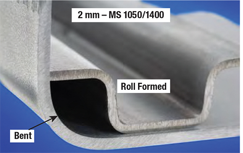 |
| Fig. 9—For martensite, the smallest bend radius is achieved by rollforming—not by a traditional stamping press. |
Adhesive wear results from microscopic welding at localized contact points between the surfaces of the tool and workpiece. Minimize adhesive wear by increasing the toughness of the tooling material, and by the proper selection and use of lubricants, tool steel and tooling surface treatments to minimize friction.
In general, the best overall tool performance is achieved through a combined balance of tool-steel toughness and wear resistance.
|
For More Information
…a free download of the Advanced High-Strength Steels Application Guidelines Version 5 is available at worldautosteel.org. It includes the latest information on metallurgy, forming and joining of these new steels.
“The guidelines are the leading AHSS information resource for engineers and press shop personnel,” says George Coates, WorldAutoSteel project manager. “It represents the steel industry’s strong commitment to not only produce new generation steels, but to actively assist automakers in applying them.” Previous versions covered metallurgy, forming and joining. Version 5.0 also reflects new content highlighting the broader materials portfolio, advanced fabrication technologies and optimized joining processes.
|
Guidelines for Cutting, Punching and Trimming
• Adequately support trimming steels and use keyed, pocketed or heeled tools where possible to avoid flexing and tipping due to side thrust.
• Consider upgrading tool steels to at least one grade level higher compared to stamping HSLA steels.
• Consider powder-metallurgy tool steels, as they often are more economical in the long run due to their low wear rate. Ceramic surface coatings will maximize tool life.
• Avoid tight corner clearances that can lead to excessive burring.
• Provide a shear angle of two- to four-times material thickness over 12 in. of trim length to reduce press tonnage and extend die life.
• Balance shear angles over the length of the cut to prevent material from being moved sideways by a single-angle shear.
|
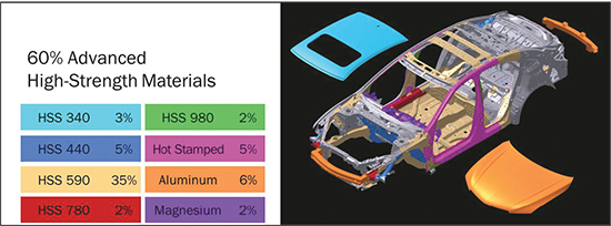 |
Fig. 10—Acura TLX
|
 |
Fig. 11—Chevy Colardo
|
 |
Fig. 12—Ford Edge
|
• To reduce die maintenance, avoid knife-edge conditions in trim steels. Perform all trimming 90 deg. to the trim surface. Design irregular shapes or notch conditions with inserts, and consider these perishable.
• Pierce holes equal to or less than sheetmetal thickness must be pierced 90 deg. to the surface. Hole diameters greater than material thickness should be pierced no more than 10 deg. off-angle.
Guidelines for Forming
• Design small replaceable sections in high wear areas.
• Die sections must have adequate aspect ratio (width-to-height ratio) with heels and keys to resist thrust forces during forming.
• Higher grades of die material, at least one tool steel grade higher, should be considered. Coat flange steels—a vanadium carbide process generally is recommended.
• Higher holding pressures are required to suppress wrinkles, which in turn increases die wear. Consider higher grades of die materials for pressure pads.
• Plan for several recuts when designing draw-form stations by increasing the thickness of the pad, post, insert, etc.
Lubrication
Lubricant breakdown can be a significant problem with higher strength steels due to higher blankholder and punch forces that result in increased friction and interface temperatures. The greater energy-absorption characteristics of AHSS (the area under true stress-strain curve) also increase part temperature. Mill oils will not provide the required lubricity for most applications; therefore stampers need to employ pre-lubes, die-process lubricants or dry-film lubricants.
A properly performing stamping lubricant must protect the tooling, tool coating and part from the abrasive effects of friction. The lubricant also should assist the flow of material to prevent wrinkles, necks and fractures. In simple operations, the lubricant requires little more than a boundary film and slip agents. More difficult operations require the use of extreme-pressure (EP) additives.
The boundary protection provided by die-process lubricants must remain intact throughout the forming process. If friction degrades the boundary film, the associated heat must activate the EP additives intended to provide additional protection. Ideally, the lubricant will delay the need for this EP protection by dissipating the die and deformation heat, protecting the boundary film and fluid viscosity.
The two most viable lubricant technologies for high-strength steel applications consist of some petroleum-based and some water-based synthetic lubricants. The most economically significant EP additives are oil-soluble and are only feasibly blended into oil-based formulas. However, the petroleum content of the lubricant retains heat and therefore provides poor cooling and heat transfer. This problem is magnified as increased friction develops as the blank material workhardens during forming.
Oils present post-processing problems such as cleaning, painting and welding. Housekeeping and environmental impact also are concerns.
Several lubricant manufacturers have developed water-based synthetics specifically for AHSS applications. These advanced synthetics comprise polymers, boundary films, thermal-resistant additives and special wetting agents. Recently, some proprietary additives have been developed to increase film tenacity, giving these lubricants “multiphase” characteristics. As frictional heat is generated during forming, the fluid forms a residual film that coats the part and the tooling. This tenacious film provides new boundary protection for later forming processes and protects punches during withdrawal.
Synthetic lubricants provide significant advantages for post-process operations, housekeeping, plant safety and environmental compliance. Often, cleaning operations can be eliminated between stamping operations and welding.
Press Equipment
The increased forces needed to form, pierce and trim higher-strength steels create significant challenges for pressroom equipment and tooling. Excessive tooling defections, damaging tipping moments, amplified vibrations and snapthrough forces can shock and break dies, and sometimes presses. Stamping higher-strength steels can affect the size, strength, power and overall configuration of every major piece of the press line, including coil-handling equipment, coil-feed systems, straightening machines and presses.
Because higher-strength materials require more stress to deform, additional servo-motor power and torque capability may be needed to pull the coil material through the straightener. Increasing the back tension between the coil-feed and straightening equipment also may be required due to the higher yield strength of the material in the loop. The loop material may try to push back against the straightener or the feed system. Insufficient back tension could cause material slippage through the straightener.
Further, as coil diameter decreases, the straightener loses the mechanical advantage it had at a larger outside diameter. Thus; the back tension force must decrease. Fortunately, manufacturers of this equipment provide electronic control options for coil-handling equipment that automatically make these compensations.
Servo-Drive Technology
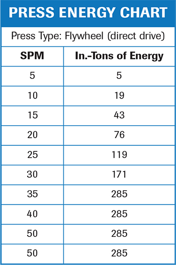
Stamping higher-strength steels requires higher blankholding forces and punch forces that result in substantial increases in frictional forces and interface temperatures. When interface temperatures reach a critical point, lubrications may breakdown and other forming and die related problems such as thermal-notching and galling can arise. When these problems occur during a production run, it would not be uncommon to reduce press speed (strokes min.) to reduce process operating temperatures and avoid thermal related forming problems.
The table to the right contains summary data extracted from an actual energy chart for a 600-ton press. It depicts the relationship between press speed and energy.
Full energy for this machine is available above 35 strokes/min. When press speed drops below this point available energy diminishes rapidly. Slowing the press may reduce thermal problems associated with the higher-strength material but there may not be enough kinetic energy left in the flywheel to carry out a continuous stamping process.
One way to address the energy shortage associated with deep-drawing higher-strength materials is to use a servo-driven mechanical press. Here, high-capacity servomotors replace the flywheel, motor and clutch/brake to provide full energy and constant torque even when speed is slowed to 1 stroke/min. Servo-drive presses also have been programmed to make multiple hits on a stamping at or near bottom-dead center (BDC), using unique tooling designs, to help reduce springback.
When comparing flywheel-drive and servo-drive press technologies, remember that there are key differences between the two technologies in term of energy—the fundamental principles of tonnage derating still apply to both. The tonnage rating of mechanical presses usually is determined at a slide position between 1⁄32 and ½ in. above BDC. The available working force (tonnage) decreases in mechanical presses as the working distance above BDC increases. This derating occurs because the relationship between the crankshaft angle and the pitman arm has reduced mechanical advantage higher up in the stroke. This is true for flywheel-drive mechanical presses and their servo-drive counterparts.
Tonnage derating and press-energy curves are specific to a given press design and its construction. They are particularly important to understand and apply to deep-drawing operations, where the drawing process can begin several inches above BDC.
Virtual Forming, and Failure Modes
The practice of engineering stamping dies generally begins with the application of computer-aided-engineering (CAE) tools to model processes in a virtual world. One of the biggest concerns with forming simulation and AHSS grades is springback accuracy. The goal of springback simulation is to provide compensation direction and magnitude for die tryout. However, the selection of different yield criteria produces varying springback results, and these results are very sensitive to anisotropy values when anisotropic yield criteria are used.
Springback calculations in metalforming simulations typically are calculated in two-step processes—residual stresses for the deformed features are predicted first, followed by predicting the elastic displacements based on the calculated relaxation of the stresses.
Two other failure modes also have been observed in AHSS stampings:
Splitting failure when bending over a sharp die radius, followed by simultaneous stretching as the material flows into the die cavity. The onset of necking may not precede this failure; this failure mode appears to occur by rapid shear-band formation, a condition that may not be predictable by the conventional FLD approach.
Failure in hole expansions and in sheared-edge stretching. Again, failures may occur sooner than predicted and may not be accompanied by appreciable necking. Some AHSS grades possess extraordinary sensitivity to sheared-edge quality. MF
Industry-Related Terms: Abrasive,
Austenite,
Bend Radius,
Bending,
Blank,
Center,
Coat,
Corner,
Die,
Drawing,
Edge,
Flange,
Form,
Forming,
Insert,
Lines,
Martensite,
Model,
Quenching,
Run,
Shearing,
Stroke,
Surface,
Tapping,
Tensile Strength,
Thickness,
Torque,
Transfer,
ViscosityView Glossary of Metalforming Terms Technologies: Coil and Sheet Handling, Lubrication, Materials