The CNC Punch Press Productivity Push
November 1, 2013 Today's punch presses are incredibly fast and accurate, sometimes beyond belief. But the real payoff from these prolific part producers comes when shops focus on sequence optimization, commonline cutting and use of special tools.
Twenty five years ago, Tim Brady started his career in metal fabricating as an applications engineer, focused on helping fabricators leverage technology to drive productivity and quality initiatives. Today he’s a product manager with Amada, specializing in CNC punch-press and tooling technology. We leveraged his background and industry experience to learn a few tips fabricators can use to optimize throughput and quality from their CNC punch presses.
Tip one, says Brady: Focus on sequencing, and the order of tool selection. “Many of the programming software products on the market feature automatic optimization routines,” he notes, “yet not every shop uses them. There are two basic programming methods. The first is used to punch out an entire, single part in a nest of similar parts, continuing on to the remaining parts in the sheet. While this proves convenient for performing a first-piece inspection, it does not als result in the most efficient program.
“The second programming method,” Brady continues, “develops the optimum tool path needed to punch an entire nest on the sheet.”
Best practice, when first-piece inspection is required: Use both programming methods, says Brady, so that the fabricator can perform a first-piece inspection and then switch to the optimized program to produce full sheets as quickly and efficiently as possible, minimizing tool changes and movement across the sheet.
Accuracy and dimensional tolerances are a whole different ballgame, and Brady also has advice here.
“To optimize accuracy from your CNC punching machine, the order in which the last few hits are made is critical,” he says. “Als make the longest parting hits the final hits in the sequence across the sheet, as you liberate parts or make microtabs. This will keep the sheet as rigid as possible. Also, start the horizontal parting tool at the top of the sheet and work toward the clamps, so that the last hits are made closest to the clamps. This also helps to ensure optimum sheet rigidity during punching.”
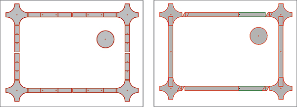 |
| Nests made with wire joints (left) and parallelogram parting tool—the parallelogram tool (right) is a much safer option, as it allows the part to break completely from the nest with the parallelogram-shaped tab adhered to the skeleton. Often, the wire adheres to the part, endangering machine operators. |
Shorten Those Tool Paths
Most fabricators understand the potential benefits from commonline punching—using a punching tool to simultaneously create, for example, the right edge of one part and left edge of another part. Material utilization climbs, as more parts, if not entire rows of parts, can be added to a sheet nest. Brady points out additional benefits of commonline punching, then explains why some fabricators have tried the technique and failed, fearful of trying again.
 |
| Here’s how the bow-tie tool looks on a sheet nest. |
“Not only does material utilization improve with commonline punching, but so does tool-path optimization,” Brady says. “By eliminating the ½ in. or larger gap between parts, tool travel is reduced. And, you’re reducing the number of hits per part, so tool life increases.”
“When do metal fabricators struggle with commonline punching?” I asked Brady. “The reasons relate back to my previous directive regarding sequencing,” he notes. “Lack of sheet rigidity is the most common problem fabricators experience with commonline punching. So, develop programs that make the longest parting hits at the end of the job, and als work toward the clamps.
“Also, when commonline punching small parts, say 6 by 6 in. or smaller, nested in a large sheet, create mini-nests of the parts within the sheet that leave a skeleton between the nests,” Brady suggests. “This will keep the sheet rigid and optimize part quality.”
Make Use of Special Tools
The increasing part complexity emanating from many a product designer often leaves programmers scratching their heads, struggling to find the most efficient method to produce parts seemingly designed by engineers with no compassion for those required to fabricate them. Tricky contours make designers happy when it comes to shaving weight, eliminating downstream assembly operations or creating cosmetically attractive parts. But they can cause fabrication operations, including punch-press processing, to bog down.
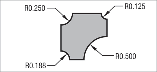 |
| This special tool, for use in an auto-index station, is designed to create four different corner radii. |
One to keep up the speed as contours become more intricate is to use special-designed punching tools. Rather than program a nibbling tool to carve a complex path, or using a group of tools to punch an intricate or multifaceted profile, “investing in a special, custom tool can easily pay off in short notice,” Brady says.
“Also, you can design a special tool to punch more than one profile,” Brady adds. “The bottom half of a tool can punch one profile and the top half a second profile—just place the tool in an auto-index station.”
As an example of where this type of tool design might shine, Brady notes corner-radiusing operations. “Rather than use separate radius tools on parts requiring varying corner radii, why not design a tool that has a different radius on each corner?” he asks rhetorically.