Share content on LinkedIn Share content on YouTube

Guidelines for Punching and Cutting

October 1, 2013
0
Comments

While punching and cutting are the most common operations performed by stamping dies, stampers do not als pay close enough attention to the sequence of operations required to maintain product quality and process stability. It generally is more cost effective to punch holes in a flat blank to avoid use of expensive cams and increased die complexity. However, when product design includes a hole in a vertical flange with critical location tolerances, the process engineer may elect to punch the hole after forming operations have been completed. It may be less expensive to punch the hole in the flat, but maintaining accurate position in the final stamping might prove difficult or impossible with such an approach.
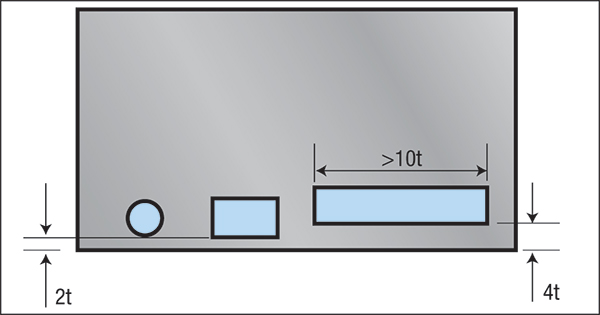
 Fig. 1

Stampers should punch holes and openings in deep-drawn parts after forming. Extensive material flow in deep-drawing operations make it very difficult to develop final hole sizes and their locations. Holes located in regions of high compression or tension will distort easily.

Additionally, stampers should punch holes located close to the edge of a blank prior to blanking. Keep a minimum distance of the punched hole to the edge of the blank edge at no less than two times material thickness. When punching slots, slot length greater than 10 times material thickness requires a minimum distance to the blank edge of no less than four times material thickness (Fig. 1).

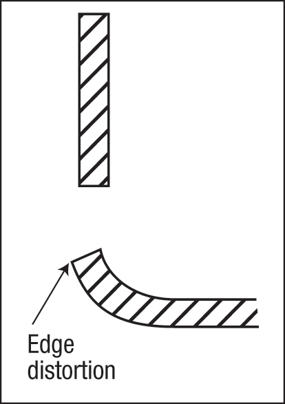
When hole-to-flange distance is specified less than 2.5 times material thickness plus the bending radius (2.5t +R), plan to punch the hole after forming to avoid distortion.

Keep slot-to-form spacing for long slots at least four times material thickness plus the bending radius (4t + R) to prevent the slot edge from distorting (Fig. 2). If additional holes also are required, punch the holes first, form the flange, and then punch the slot.

When large and small holes are located close to each other, punch the larger hole first. This prevents distortion of the smaller hole caused by the cutting action of the larger punch.

Edge Quality

The cut-edge quality is critical when forming stretch flanges and flanged holes. Here we require sharp tools and proper die clearances to produce edges that will stretch uniformly and without fracturing prematurely.

 Fig. 2

Hole flanges and extrusions start with a punched hole in a flat surface of the workpiece. The hole is subsequently expanded to the required inside diameter, usually in one hit. The wall height results from the punched hole diameter, the quality of the hole edge, the diameter of the flanged hole and the amount of allowable wall thinning. For maximum hole flange and extrusion heights, the best solution is to create the hole in three singular steps: punch, shave, and coin the bottom side prior to forming the extrusion.

For most materials, shaving typically removes about 10 percent of material thickness. This provides good surface finish and leaves enough material in the scrap ring for slug retention. This is an important point, because most metalformers consider slug retention to be the most common problem associated with shaving operations.

Angular Punching

 Fig. 3

Some irregular-shape stamping geometries may require tipping of the part in the die, because there is a limit when it comes to punching on an angle. A common practice has been to limit cutting and punching angles to a maximum of 15 deg., to avoid the complex guiding and support systems needed to control punch, stripper and part deflection. When punching angle exceeds 15 deg., it generally is less costly and more reliable to add an additional operation or use a cam.

Stampers also may struggle with hole-size accuracy when performing angular punching. The punch cuts a hole opening in the part that on a slight angle, but the part print requires the hole size to be measured perpendicular to the part surface. As a result, the shape and size of the punch will be different than the final hole diameter (Fig. 3).

Progressive-Die Strip Carriers

When cutting stretch carriers in progressive-die strips, be sure to cut the inside carrier first—cut only half- through the material and use a pressure pad that bottoms out in the die cavity. The bottoming pad ensures the cut will only penetrate half through the material thickness. This eliminates having to push the blank back into the punched opening, which usually leads to slivers in the die. Cut the outer carrier next, using the same technique.

Punch pilot holes in progressive strips undersized if the final diameter is critical. The hole may be punched larger or shaved in the final operation to establish its final size.

Applying these cutting and punching guidelines should help improve product quality and process reliability for many stamping operations. MF
Industry-Related Terms: Thickness, Bending, Blank, Blanking, Bottoming, Die, Edge, Flange, Form, Forming, Scrap, Slot-to-Form, Slug, Stripper, Strips, Surface
View Glossary of Metalforming Terms

Technologies: CNC Punching, Quality Control

Comments

Must be logged in to post a comment.
There are no comments posted.

Subscribe to the Newsletter

Start receiving newsletters.