There are two s to reduce weight. One is to use lighter-weight materials such as aluminum. Another is to remove material from the stripper by drilling holes or milling pockets in noncritical areas. Drilling holes can reduce weight without sacrificing too much strength. When strategically placed, drilled holes can provide venting of air and lubricants to further enhance quick stability.
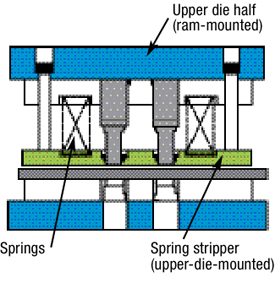
In high-speed stamping it is important to minimize stripper travel. Excessive stripper travel means springs must compress further than necessary, generating additional heat that leads to premature failure or breakage.
 |
|
Fig. 1—Spring stripper
|
Stripper bolts and spools will travel longer distances at higher speeds, meaning that their heads will impact the bottom of the counterbored holes with greater force, leading to damage or breakage if the proper fastener was not specified for the increased loads. In addition to creating punch wear and galling problems, excessive stripper travel also reduces the amount of time available to feed coil material through the die.
A spring stripper also helps to absorb shock produced by snapthrough loads and minimizes the shock produced by the stripping of a piece part off of the punch point.
 |
|
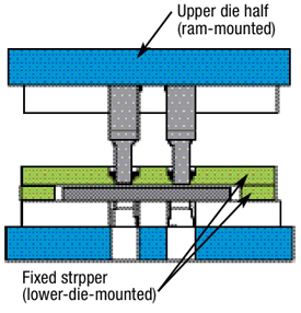
Fig. 2—Fixed stripper
|
Another to reduce the upper-tooling weight is to use fixed strippers, sometimes referred to as bridge or positive strippers (Fig. 2). These are not commonly used for thin parts in general-purpose or high-volume production applications, but since they have no moving parts and do not contribute to the ram’s mass, they may prove beneficial in very high-speed operations. But they do have disadvantages.
Fixed strippers cannot hold the stock flat and cannot absorb impact or snapthrough loads. Distortions may occur in the piece part around the punched hole where the material was stripped. And because the part (coil) material is not held down by a fixed stripper, it can slide when punched or formed, resulting in punch-point breakage or poor part quality.
Sudden unloading of cutting pressure on the punches and part material at snap-through can generate enough shock to break punch heads. When the punch retracts the part tends to buckle, binding the part on the end of the punches. This increases stripping pressure that can eventually lead to chipping of the punch face.
The subject of high speed is very involved and highly specialized. In addition to the topics already addressed in this limited series, other factors are involved. Among these are: die positioning in the press to minimize tipping moments; press stopping times (the press must stop before completing one stroke); material feeding; scrap removal; part removal; rotary balance of reciprocating press components; and in-line welding to enable nonstop stamping, the scope of which is too great—and my experience too narrow—to address in this column.
If you want more information on high-speed stamping, Dayton Progress provides useful and simple to understand literature on its website. This material was an excellent source in preparing this series. I placed a link on my website: www.toolingbydesign.com. Just go to the Tooling Tech page and click on High-Speed Stamping—Dayton Progress.
I discovered that literature specific to high-speed stamping is rather scarce and difficult to find. If you have any sources you would like to recommend, send me an e-mail. I will publish recommendations in a future column. MF
Industry-Related Terms: Compress,
Die,
Draw,
Drawing,
Form,
Piercing,
Ram,
Scrap,
Stripper,
Stripping,
StrokeView Glossary of Metalforming Terms Technologies: Bending