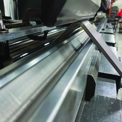
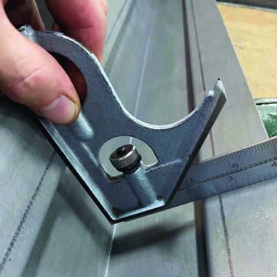
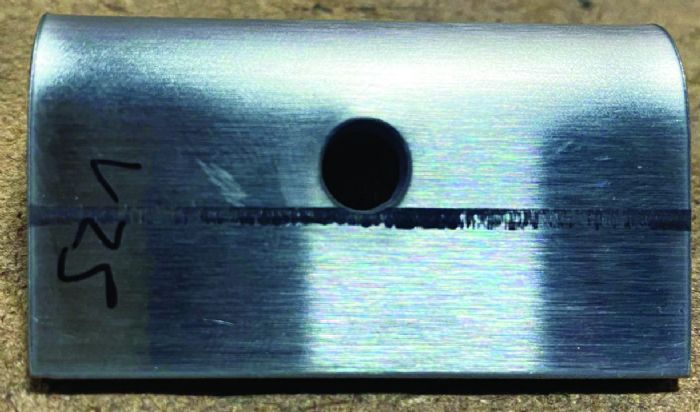
 Bend-line slit. Another possible solution is “bend-line slitting,” a relief cut on the bend line. The idea is to insert a weak point purposefully where the material should form on the bend line instead of the feature. This keeps the bend line from pulling and eliminates the pucker. Fig. 3 shows a slit longer than required. The slit width only must be as wide as the feature. Again, this was bent in a 0.984-in.-thick, 88-deg. V die. Slits may not be acceptable in the finished part, thus welding and cleaning the area may be necessary, which adds downstream processes.
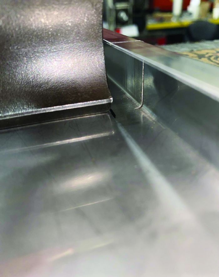 Another example of a suitable alternative for a bend-line slit, is when the tooling ends before the material edge. Often, return flanges can pose interference issues with the tooling. Horn punches, or ear tools, are cut away to allow access to some of these shapes (Fig. 4). But what if they are not on hand or they do not match the tooling geometry? Simply slit the bend line from the material edge to the end of the tool. This also works for lower-die gaps when the return flanges descend.
Downsized V opening. These are great, but what if blanking already has occurred? An option could be a smaller-than-standard V opening. Recommended V openings are based on achieving the best, most consistent results. However, stepping down a size or two may reduce the feature interference enough to avoid costly rework. Smaller V openings will increase springback, tool-marking and tonnage requirements. Always double-check the bend’s tonnage requirements and the tool’s and machine’s ratings to avoid overloading.
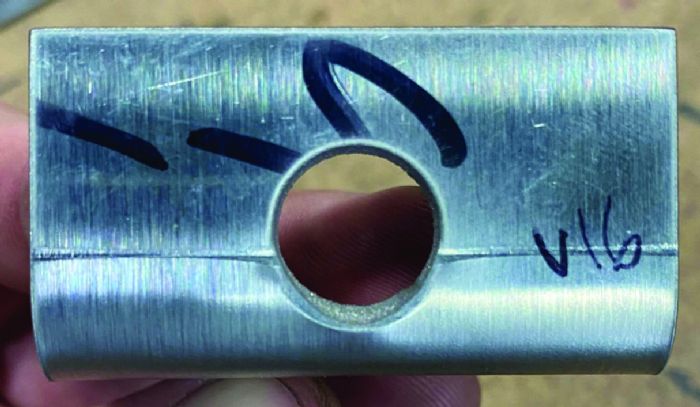 The example in Fig. 5 shows a 0.630-in.-thick, 88-deg. V die, which minimized the amount of deformation but did not eliminate it. Tooling geometry also affects the amount of blowout. A larger shoulder-radius die or an acute die will allow the material to slip earlier in the forming process, worsening any potential blowout.
Support the sheet. If a downsized die opening just doesn’t cut it, supporting the sheet through the bending process may be the only way forward. A rotary cam die has rotating semicircular inserts that allow the material to glide across the working surface while keeping pressure on the blank. This constant contact of the sheet to a hard surface usually prevents deformation, though the operator should maintain a minimum distance from bend line to the feature. No post-processing is required.
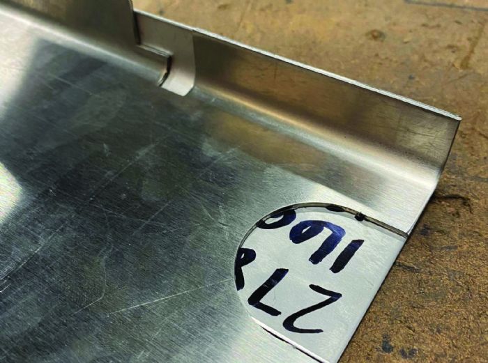 Use sacrificial backer. No rotary cam die available? The operator can try using scrap material as a “sacrificial backer,” placing a blank placed under the workpiece intended to add support through the bending cycle (Fig. 6). The backer must have strength greater than or equal to the workpiece, or the backer will tear and the workpiece will deform. Using a different material or thickness may result in varying degrees of springback between the workpiece and backer. Ideally, use a backer of the same material length, thickness, grade and temper as the work material. A larger-than-normal V opening may be required to account for the increased thickness of the part and backer. In the example, a 16-gauge stainless-steel part with a short flange would not come around without support from a backer. The backer is the same material as the workpiece. The punch nose radius measures 0.236 in. and the 88-deg. V die is 0.787 in. thick.
Windows, Miters and Radii
Windows, or cutouts, deform similarly to holes when the window edge resides within the die space and not perpendicular to the bend line. Often a window edge is positioned parallel to the bend line. This will pull the dimension considerably as it blows out. The window length represents an additional variable to consider when assessing the likelihood of a deformation occurring. Longer windows will encounter more deformation because more material will fall into the die space.
Miters pull the bend line toward the area of least resistance. This is the side with the least amount of material in the die space. When possible, at the start of the forming process, force the bend to pull toward the stops, keeping pressure against them rather than away.
The resolutions to managing distortions in windows are much the same as with holes, with a few notable differences. Rotary cam dies and sacrificial backers help support the bend and reduce the pulling effect. Bend-line slitting creates a fold point by introducing a point of least resistance. Piloting is not much of an option here, as a noncircular shape usually cannot be added easily downstream unless the part will be machined on a mill or EDM afterward. However, this does offer another similar pre-blanking resolution.
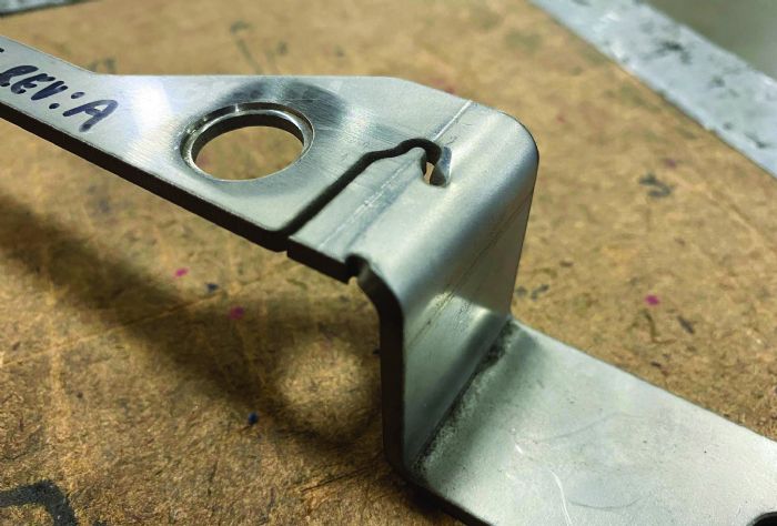 Unslitting, silhouetting, tabbing. These all are terms for intentionally not cutting feature lines in the blanking process to keep the skeleton attached to the workpiece for additional support during forming (Fig. 7). Lines running perpendicular can be cut without worry about deformation. Lines running parallel to the bend line are not cut. Depending on the amount of allowable deformation, miters and radii may be cut.
Removal of the tabbed skeleton requires designing some space inside of a window feature to allow for the cutting operation after forming. The example shows a unique feature that would not come around without the use of an unslit.
Don’t like the idea of adding a downstream process just for miters? The benefits here are twofold. Often, miters reduce the distance between the backgauge fingers down to a fraction of the overall bend length. Tabbing a square skeleton to the mitered edge can increase this distance, increasing backgauge accuracy.
Minimum Flange
Often, rotary cam dies can catch short flanges. Check with the tooling supplier for the minimum flange size that the tool can bend without catching the flange. Forming a flange shorter than this minimum can cause the edge to slip inside of the rotating inserts and damage the tool. A common range of around 60 to 70% of the die width is recommended.
While a sacrificial backer likely won’t bring a short flange around on its own, it can help support sections of short flange length on a bend. Unlike a hard-surfaced rotary cam die, a backer is forming (and deforming) along with the workpiece. The stiffer the backer, the less it will deform and the more likely the workpiece will keep shape.
Machined Surfaces
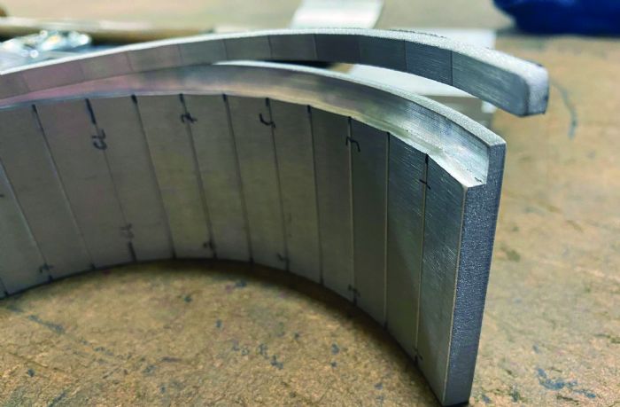 Press brake operators can prevent deformation on a machined surface by using a sacrificial blank to take up the space (Fig. 8). With a machined surface on top of the part, the blank will act as a punch wrapper, making the pushing radius equal to the punch nose plus the blank’s material thickness. With a machined surface on the bottom of the part, the blank will act more as a sacrificial backer and support the forming process, as long as it bridges the die gap. For step-bending, a set of C clamps may seem like a good idea but the bends of the workpiece and sacrificial blank may elongate at different rates. Double-sided tape can help keep the blank and workpiece in unison while providing a small amount of give to cover the spread.
Finding Balance
These approaches often come with additional processes that add cost to the final part. Designers and fabricators must work together to create useable parts at a reasonable price. Designers should avoid placing features near bend lines whenever possible. If a close feature is required, a fabricator can use one of these tricks of the trade, salvaging an otherwise unusable part. This list is not all-encompassing. Should you find yourself in a similar situation, perhaps you can develop your own process for managing deformation. MF
Creative Approaches to Common Press Brake Challenges, Part 1: Step Bending
Creative Approaches to Common Press Brake Challenges, Part 3: Self-Inspection at the Brake
Creative Approaches to Common Press Brake Challenges, Part 4: At-the-Brake Fixes
Industry-Related Terms: Bending,
Blank,
Blanking,
Bridges,
Cam,
CAM,
Die,
Dimension,
Edge,
Flange,
Form,
Forming,
Insert,
Lines,
Scrap,
Springback,
Stainless Steel,
Surface,
Thickness,
Forming,
Forming,
Press Brake,
WeldingView Glossary of Metalforming Terms Technologies: Bending
 A common problem a press brake operator encounters is deformation of a feature that resides too close to the bend line. This could be a hole, window or even the part edge. A feature in proximity to the die space could negatively affect the bend. As a piece of sheet metal folds, the bend line will tend to flow toward the area of least resistance.
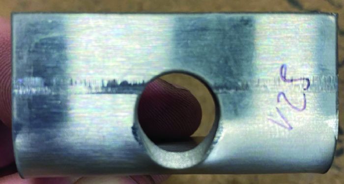
  When a designer creates a sheet metal part intended to be mounted to an object, inevitably, it will have holes. The holes may be tapped or designed for a bolt. Maybe they’re only plug-weld holes. In Fig. 1, 12-gauge stainless steel with a ½-in.-dia. hole dimensioned ⅛ in. from the bend line was bent in a 0.984-in.-thick 88-deg. V die. The hole has deformed substantially as a result. Some hole deformation can be acceptable, depending on the application, but when it’s not, a fabricator must find a resolution.


 Bend-line slit. Another possible solution is “bend-line slitting,” a relief cut on the bend line. The idea is to insert a weak point purposefully where the material should form on the bend line instead of the feature. This keeps the bend line from pulling and eliminates the pucker. Fig. 3 shows a slit longer than required. The slit width only must be as wide as the feature. Again, this was bent in a 0.984-in.-thick, 88-deg. V die. Slits may not be acceptable in the finished part, thus welding and cleaning the area may be necessary, which adds downstream processes.
  Another example of a suitable alternative for a bend-line slit, is when the tooling ends before the material edge. Often, return flanges can pose interference issues with the tooling. Horn punches, or ear tools, are cut away to allow access to some of these shapes (Fig. 4). But what if they are not on hand or they do not match the tooling geometry? Simply slit the bend line from the material edge to the end of the tool. This also works for lower-die gaps when the return flanges descend.
 The example in Fig. 5 shows a 0.630-in.-thick, 88-deg. V die, which minimized the amount of deformation but did not eliminate it. Tooling geometry also affects the amount of blowout. A larger shoulder-radius die or an acute die will allow the material to slip earlier in the forming process, worsening any potential blowout.
 Use sacrificial backer. No rotary cam die available? The operator can try using scrap material as a “sacrificial backer,” placing a blank placed under the workpiece intended to add support through the bending cycle (Fig. 6). The backer must have strength greater than or equal to the workpiece, or the backer will tear and the workpiece will deform. Using a different material or thickness may result in varying degrees of springback between the workpiece and backer. Ideally, use a backer of the same material length, thickness, grade and temper as the work material. A larger-than-normal V opening may be required to account for the increased thickness of the part and backer. In the example, a 16-gauge stainless-steel part with a short flange would not come around without support from a backer. The backer is the same material as the workpiece. The punch nose radius measures 0.236 in. and the 88-deg. V die is 0.787 in. thick.
 Unslitting, silhouetting, tabbing. These all are terms for intentionally not cutting feature lines in the blanking process to keep the skeleton attached to the workpiece for additional support during forming (Fig. 7). Lines running perpendicular can be cut without worry about deformation. Lines running parallel to the bend line are not cut. Depending on the amount of allowable deformation, miters and radii may be cut.
  Press brake operators can prevent deformation on a machined surface by using a sacrificial blank to take up the space (Fig. 8). With a machined surface on top of the part, the blank will act as a punch wrapper, making the pushing radius equal to the punch nose plus the blank’s material thickness. With a machined surface on the bottom of the part, the blank will act more as a sacrificial backer and support the forming process, as long as it bridges the die gap. For step-bending, a set of C clamps may seem like a good idea but the bends of the workpiece and sacrificial blank may elongate at different rates. Double-sided tape can help keep the blank and workpiece in unison while providing a small amount of give to cover the spread.