Bending Variations
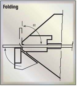
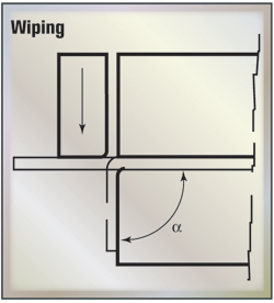
In bending, a distinction can be made between four variations: air bending, bottoming, coining and three-point bending. Characteristic of these: The sheet is pressed by a top tool into the opening of the bottom tool (Fig. 3). As a result, sheetmetal on each side of the bend is lifted, causing problems such as sagging and folding with large sheets. In that case, folding or wiping is preferred, although sheet-follow supports also can be used with the press brake to alleviate this. Where bending involves positive and negative angles, folding offers more flexibility. The significant advantages offered by press brakes are increased speed and flexibility.
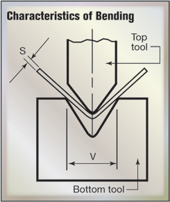 |
| Fig. 3 |
Air Bending—With air bending, the top tool presses a sheet into the V opening in the bottom tool to a predetermined depth, but without touching the bottom of the tool (Fig. 4). This is a type of three-point bending, where only the bending radii of the top and bottom tools contact with the sheet. The punch radius of the top tool and the V angle of the bottom tool need not be the same. In some cases, a square opening replaces the V opening in the bottom tool—especially given today’s adjustable bottom tools. The combination of top and bottom tools, therefore, can be applied universally, meaning that with a single combination, various products and profile shapes can be produced simply by adjusting the press-stroke depth. In other words, with a single combination of tools, multiple materials and thicknesses can be bent in a range of bend angles. This makes air bending a highly flexible technique.
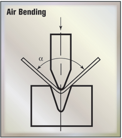 |
| Fig. 4 |
It also means that the number of tool changes can be limited considerably, enhancing productivity. Another advantage: Less bend force is required, meaning less bulky tools and resulting in extra allowance in product design.
One limitation of air bending: It is less precise than processes where sheet fully maintains contact with tooling. The stroke depth must maintain high accuracy, and variations in sheet thickness and local wear on the top and bottom tools can result in unacceptable deviations. Variations in material properties also affect the resulting bend angle due to springback. To achieve maximum angle accuracy with air bending, a value is applied to the width of the V opening, ranging from 6S (six times material thickness) for sheets to 3 mm thick to 12S for sheets more than 10 mm thick. A rule of thumb: V=8S.
Air bending boasts angle accuracy of approximately ±0.5 deg. Unlike with bottoming and coining, bend radius is not determined by tool shape, but depends on material elasticity (Fig. 4). Normally, the bend radius resides between 1S and 2S. Based on its flexibility and relatively low tonnage requirements, fabricators are moving more toward air bending as the preferred forming technique. The disadvantages of this technique related to quality are remedied by taking special measures—angle-measuring systems, clamps and crowning systems that are adjustable along the x and y axes, and wear-resistant tools.
 |
| Fig. 5 |
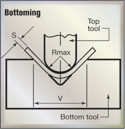
Bottoming—Bottoming, a variation of air bending, presses the sheet against the slopes of the V opening in the bottom tool (Fig. 5), with air between the sheet and the bottom of the V opening. In this case, the punch radius and the V-opening angle are directly linked, meaning that bottoming does not offer the same flexibility as air bending. Every bend angle and every sheet thickness requires a separate tool set, and the same often applies for different materials due to springback differences and compensation required in the tool. For bottoming, the optimum width of the V opening (U-shaped openings cannot be used) is 6S for sheets to thicknesses of about 3 mm, increasing to 12S for sheets more than 12 mm thick. Again, the rule of thumb: V=8S. The minimum acceptable bending radius for sheet steel ranges from 0.8S to 2S, although material quality plays a role. And with soft materials such as copper alloys, the radius of the bend angle may be much smaller—a lower limit of 0.25S is possible.
For larger bend radii, bottoming requires tonnage roughly the same as for air bending for larger bend radii. Smaller radii require force as much as five times greater when bottoming. This brings the advantage of greater accuracy. The resulting bend angle is wholly determined by the tool, with the exception of springback, for which a correction can be made. Note that bottoming results in less springback than when employing air bending. Theoretically, angle accuracies with bottoming approach ±0.25 deg. But because control and adjustment possibilities on press brakes have increased considerably, even on less-expensive machines, air bending increasingly is preferred to bottoming.
 |
| Fig. 6 |
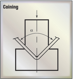
Coining—With coining, the top tool crushes sheet into the opening of the bottom tool, down to the bottom of the V opening (Fig. 6). Coining requires many times the bend force of air bending and bottoming—normally, five to 10 times higher tonnage, and in some instances, 25 to 30 times higher. But coining offers the advantage of a high level of precision. Because of the extremely high pressure exerted on the punch tip into the material, permanent deformation occurs throughout the entire cross-section of the sheet, with springback reduced to virtually zero. As the punch and V-die angle are identical, the desired bend angle can be easily selected, and variations in sheet thickness and material properties have little or no effect on coining results. The high level of force and the permanent deformation mean that the minimum achievable inside radius—starting at 0.4S—is less than with air and bottoming, with the width of the V opening required usually about 5S. A wider V opening would mean that depth must be greater in order to achieve the same bend angle. In general, coining costs more than air bending and bottoming, therefore, it is sporadically applied, and even then only for thin sheets.
Three-Point Bending—A relatively new bending technique, three-point bending is considered by some to be a special variation of air bending. This technique employs a special die where its bottom tool can be precisely adjusted in height via a servo motor. The sheet bends over the bend radii of the die until it touches bottom, with the bend angle decreasing as the depth of the die bottom increases. The bottom height of the die, as already indicated, can be determined very precisely (±0.01 mm), with corrections made between the ram and the upper tool using a hydraulic cushion to compensate for deviations in sheet thickness. As a result, the process can achieve bend angles with precision of less than 0.25 deg. Advantages of three-point bending include high flexibility combined with high bending precision. Obstacles include high costs and a limited range of available tools. As a result, this technique, for the time being, is limited to highly demanding niche markets where the additional costs are outweighed by the stated advantages.
Difficulties in Press-Brake Bending
Anisotropy. Sheet material itself, its properties and especially the variations in these properties, can influence the press-brake-bending process. Sheetmetal, produced on large rolling mills, undergoes hot or cold rolling to reach final thickness: hot rolling typically for thicker sheet and cold rolling for thinner sheets due to the high loss of heat and difficulty in maintaining constant temperature in thin material. Also, cold rolling better controls thickness tolerances and causes hardening of the surface layer.
Rolling stretches the crystal structure, causing material to acquire different mechanical properties across its length than across its width. In other words, the material becomes anisotropic, and this affects the subsequent processing. During bending, this can lead to variations in the bend angle. Apart from this anisotropic nature, unavoidable variations occur in material properties as a result of minute differences in material composition and rolling conditions. This also results in variations in stress/ strain curves, not only between different batches of sheet materials, but even within a single batch.
Springback. Springback is the phenomenon by which sheet rebounds on either side of the bend after the bending tool has been removed. Why? In the center of the sheet—not exactly the geometrical center, but close to it—resides a zone with low stress in which, even under large bend forces, only elastic deformation occurs. This part of the sheet’s cross-section, therefore, wants to return to its original shape after bend force is lifted. The extent to which springback occurs depends on the nature of the sheet material: The stiffer the material, the greater the springback. Soft materials exhibit springback limited to no more than 0.5 deg., and steel to 1 deg., but springback in stainless steel can amount to as much as 3 deg.
 |
| Fig. 7 |
Bend angle also is a determining factor. The smaller the relative effect on the elastic area in the neutral zone, the smaller the springback. This is the case with small bend angles and small bend radii (meaning a sharp tool). For example, a steel sheet 0.8 mm thick bent with a bend radius of 1S exhibits springback of 0.5 to 1 deg. The same sheet bent with a bending radius of 77S results in springback of as much as 30 deg., according to Steve Benson in his book, Press Brake Technology: A Guide to Precision Sheet Metal (published by the Society of Manufacturing Engineers). With a leg length of 100 mm, each degree of deviation will mean that the end of the sheet will have a spatial deviation of 1.7 mm. For post-processing, such as robotic welding, a deviation of this size will soon exceed acceptable tolerance limits. In practice, it is relatively easy to correct for springback when bending a sheet, providing that influential parameters are known. For calculating springback for cold-rolled steel, a formula offered by Benson is D = R / (2.1 x S) where R is the radius of the angle in mm and S is the sheet thickness in mm. Using this formula, a steel sheet 0.8 mm thick, and given a bend radius of 20 mm and a bend angle of 90 deg., has a springback value of 11.9 deg. To calculate springback for other materials, Benson uses a correction factor (0.5 for copper, 0.75 for hot-rolled steel and 2.0 for stainless steel).
Keep in mind that under certain air-bending conditions, negative springback can occur, particularly when employing dull tools in combination with a large punch angle as deformations then can occur in the sheet between the punch and die surface. When coining, given high pressing pressure and a sharp top tool, this tool can press into the sheet past the neutral zone. In that case, the plastic phase is achieved everywhere and springback is reduced to virtually zero.
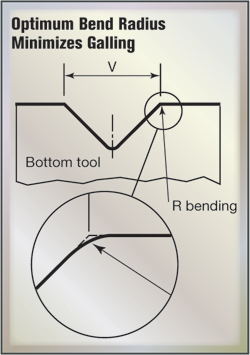
Galling. Galling of the bend tool—particles of material or part flakes cling to spots on the tool during bending—is especially a concern with the bend radii in the bottom tool. Galling can result in damage to tools and to the sheet surface. This problem can be minimized by selecting an optimum bend radius for the V-die (Fig. 7) and by hardening the relevant bend radius. Hardened sursurfaces are much less sensitive to galling.
 |
| Fig. 8 |
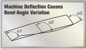
Machine Deflection. When high tonnage is exerted, deflection unavoidably occurs lengthwise in the top and bottom tools. As a result, the top and bottom tools no longer remain parallel during the bend process, bringing variations in the bend angle over the length of the product (Fig. 8). This adversely affects post-bend processes such as robotic welding. In the past, this problem often was remedied by shimming the bottom tool to acquire a crowning that compensated for the deflection. Today, computer-controlled or centrally adjustable crowning systems quickly and accurately compensate for deflection over the entire machine length.
MF
Information for this article excerpted from the Press Brake Productivity Guide, published by Wila USA, Hanover, MD. Tel. 888/696-9452.
Industry-Related Terms: Bending,
Bottoming,
Case,
Center,
Coining,
Die,
Form,
Hydraulic Press,
Forming,
Layer,
Ram,
Stainless Steel,
Stroke,
Surface,
Thickness,
Tolerance,
Air Bending,
Alloys,
Bend RadiusView Glossary of Metalforming Terms
See also: Wila USA
Technologies: Bending


 Video
Video