


 That can be challenging, however. Following are tips on how to check a part at the brake.
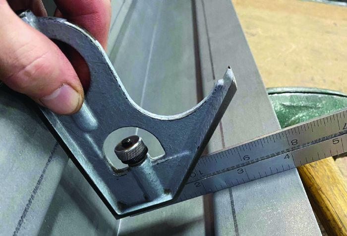 Looking ahead allows you to identify and plan for any potential pitfalls.
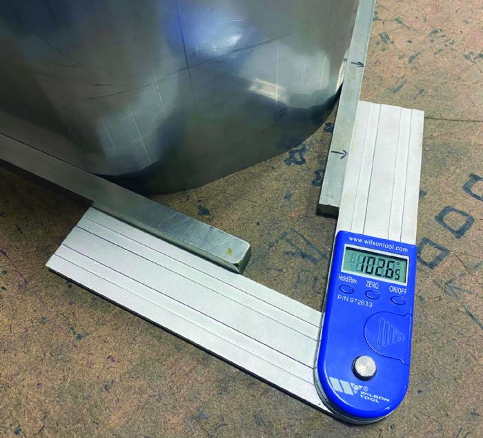 Press brake operators have several check tools at their disposal, including gauge blocks, square blocks, height gauges and marble tables.
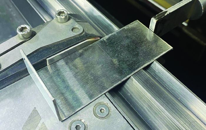
Use the whole square. Squares come in many different varieties. Some can measure 45 and 135 deg. Check for parallelism between two offset flanges. Squares also can be used as a depth probe or a length gauge with a set dimension.
 Use extensions. Occasionally, hand tools commonly used in the trade aren’t long enough to perform needed measurements. Enter extensions. A few lengths of square bar will extend the gauging surface of hand tools to obtain those pesky, hard-to-reach dimensions. The opposite also is true; custom gauges can be cut to fit any shape.
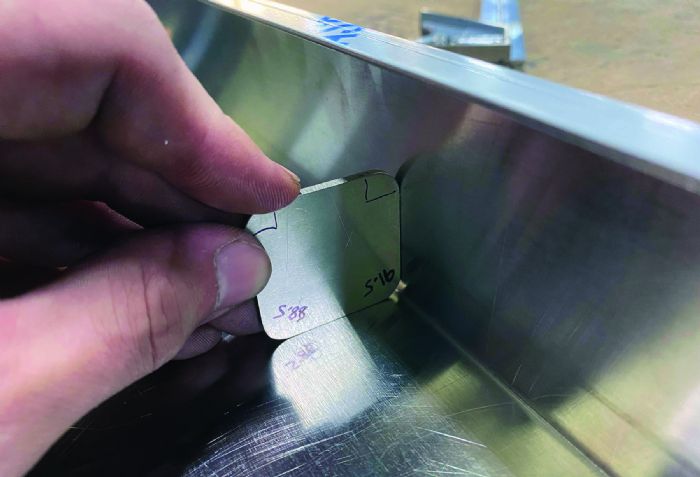
Overlay the part on a full-scale drawing. Full-scale drawings are at a 1-to-1 ratio. In other words, they are “real-world” sized. Use them as inspection tools. Place a drawing of the part’s silhouette on a surface plate and lay the part over the top of the drawing, making sure that the part exactly matches the drawing underneath. Apply a thin layer of clear packaging tape to help prevent tearing and to keep grime accumulation from wearing out the drawing.
This quick, budget-friendly solution can be used for both inspection and layout. Potentially the biggest boon is that operators can work with parts that have critical, hard-to-gauge bend lines.
 In a similar manner, use a full-scale drawing to aid layout work. This only requires adding the bend lines on top of the silhouette, extending past the part edge. Once the workpiece is placed on top of the drawing, bend lines quickly can be transferred.
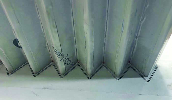
Check with a profile gauge. An operator also can use a full-scale inspection gauge. It comes in all shapes and sizes and is not as limiting as its paper counterparts. Just like a full-scale drawing, it can be used to check bend radii and lengths, as well as layout bend lines. Custom-made inspection gauging is more versatile. It is rigid and can fit in spaces that otherwise would be too tight for a traditional hand tool. Verifying a profile becomes efficient.
Gauge against a surface plate. A flat table used for inspection is called a surface plate. Usually cut from granite, this precision measuring instrument provides a reference point during inspection processes. Due to their cost, these tables often are reserved for the inspection department. But a small section of granite or similarly smooth stone from a countertop installer might prove to be sufficient. Absent of that, any extremely flat plate that doesn’t flex can work to check a press-brake-bent part.
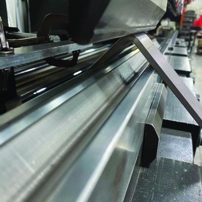
 Surface plates help not only during normal dimensional and angular inspection, but also when forming step bends, cones and transitional parts. The plate provides a flat plane to brace a workpiece against. Any deviation from the expected shape will show as a gap between the workpiece and the plate.
Transitions are all about planes. The opening must match at the correct angle to its associated plane. If the angle to the plane is wrong, it will change the way that the workpiece meets the plane, thereby changing the shape of the opening.
Full-scale gauges, protractors, height gauges and surface plates work in unison to provide the required data to massage a step-bent opening into place on a specified plane at the correct angle.
Side stops. A side stop has two main purposes. First, it acts as a gauge to keep the workpiece in a given location, left to right on the machine. This helps increase accuracy and speed, mainly on high-volume runs. Second, a side stop can keep short-bend-length parts in a specific orientation to the bend line, usually perpendicular. This can be as simple as holding a square against the die or as fancy as setting a specialized side gauge at any angle between 0 and 90 deg.
Watch for material edge deformation on successive bends. This blowout on the side of a bend may occur at the point of contact between the workpiece and the side stop. The result: a perpendicular first bend and a slightly out-of-square second bend.
Pin gauging. In this instance, pin gauging does not refer to the inspection of a hole diameter, but rather, the process of gauging the workpiece using a round pin instead of a normal backgauge finger. But why would an operator need to use pins?
Pins are most effective when a critical hole-to-bend dimension must be held or when the workpiece edges are unsuitable for a common finger. Some backgauges come with high-precision pins preinstalled on the fingers, but they also can be fashioned quickly to retrofit a pinless backgauge.
One note of caution: Always push against the pins; never pull. Pushing allows space behind the hole for the pin to clear as the part forms. Pulling orients the rear of the hole against the pin, crashing the part into the pin as it tries to form.
Line Bending
Bending using demarcation is a skill that too few operators have acquired. The ability to steadily hold a part and move it ever so slightly forward and back to align it with the tooling is highly underrated.
Line bending, implemented in the right processes, can reduce setup time, increase accuracy and prevent mistakes. Resetting a manual backgauge or zeroing it to match a set of planer-style tools on small batch orders can take significant time. Adding the bend lines upstream in the CNC blanking process can prevent lost time at the brake laying out by hand. Brake operators often apply bend lines at the brake as a doublecheck when something looks awry. Bend lines applied to the part help ensure bending from the correct side and at the correct location.
Many different line-bending methods are employed. Some common examples include center-punch dots, triangular notches, etch lines, scribe lines, marker lines, laser-alignment tools and “kissing” the part to leave a witness mark. Finish requirements or forming restrictions play a factor. An operator probably wouldn’t use center-punch dots on a 20-gauge, mirror-finish, stainless-steel transition because it would require additional finishing time. A 12-gauge 6061-T6 aluminum bracket wouldn’t warrant scribe lines because they would increase the likelihood of cracks and tears.
Add reference lines if the punch radius does not lend itself to visual gauging. Interpolation is a method of using known data to estimate an unknown value. What does that mean for bending purposes? Simply put, if operators can see two points, they can estimate the distance between them with a relatively high degree of accuracy. So, pick another landmark to use and add a reference line, but be sure not to mistake the reference line for a bend line.
The shoulder edge of the bottom die often is the easiest to calculate for a layout. Figuring the distance between the die shoulder and a layout line is similar to estimating using a vernier caliper. The viewing angle affects the estimation. Often, operators stand to the side of the part to get a view parallel to the tooling, thus lowering the angular skew.
Experienced press brake operators frequently develop an intuition for when an operation starts to drift or when a part just looks off from a few feet away. Visual inspection of the parts while stacking for shipment can reveal variations that, otherwise, would go unnoticed. MF
Creative Approaches to Common Press Brake Challenges, Part 1: Step Bending
Creative Approaches to Common Press Brake Challenges, Part 2: Managing Feature Deformation
Creative Approaches to Common Press Brake Challenges, Part 4: At-the-Brake Fixes
View Glossary of Metalforming Terms
Technologies: Bending
Comments
Must be logged in to post a comment. Sign in or Create an Account
john l. WED, FEB 12, 2025 @ 10:37 AM
great read!!!!
 Bending
Creative Approaches to Common Press Brake Challenges, Part 4...
Justin Talianek April 25, 2025

 Bending
BLM Group USA Names Adelman Head of Product Group
Friday, May 16, 2025